Method and device for receiving PTRS for cancelling phase noise in wireless communication system

a wireless communication system and phase noise cancellation technology, applied in the field of wireless communication systems, can solve problems such as significant path loss, and achieve the effects of accurate decoding, improving the efficiency of signal transmission for phase noise cancellation, and improving the phase noise cancellation procedur

Active Publication Date: 2019-10-15
LG ELECTRONICS INC
View PDF20 Cites 9 Cited by
  • Summary
  • Abstract
  • Description
  • Claims
  • Application Information

AI Technical Summary

Benefits of technology

[0017]According to the present specification, received signals can be accurately decoded by improving a phase noise cancellation procedure performed by a user equipment (UE) in a wireless communication system.
[0018]According to the present specification, a method for improving efficiency of signal transmission for phase noise cancellation can be provided.
[0019]According to the present specification, receiving-side operation can be improved by providing information on the signal transmission for the phase noise cancellation.
[0020]According to the present specification, a PTRS allocation method can be provided.
[0021]According to the present specification, a method of transmitting a signal for the phase noise cancellation by considering compensation for phase noise and reference signal overhead can be provided.

Problems solved by technology

Due to such a center frequency feature, significant path loss may occur in a shadow area in the mmWave communication system.

Method used


Image

  • Method and device for receiving PTRS for cancelling phase noise in wireless communication system
  • Method and device for receiving PTRS for cancelling phase noise in wireless communication system
  • Method and device for receiving PTRS for cancelling phase noise in wireless communication system

Examples


Embodiment Construction

[0029]Although the terms used in the present invention are selected from generally known and used terms, terms used herein may be varied depending on operator's intention or customs in the art, appearance of new technology, or the like. In addition, some of the terms mentioned in the description of the present invention have been selected by the applicant at his or her discretion, the detailed meanings of which are described in relevant parts of the description herein. Furthermore, it is required that the present invention is understood, not simply by the actual terms used but by the meanings of each term lying within.

[0030]The following embodiments are proposed by combining constituent components and characteristics of the present invention according to a predetermined format. The individual constituent components or characteristics should be considered optional factors on the condition that there is no additional remark. If required, the individual constituent components or charac...


PUM


Abstract

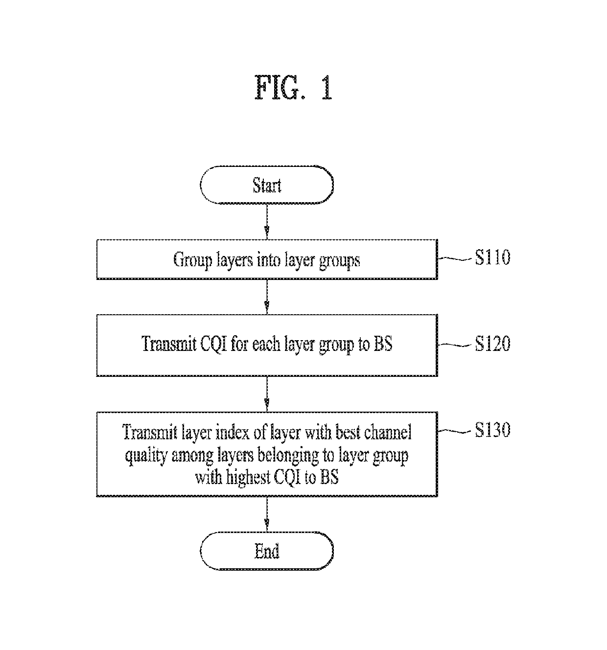
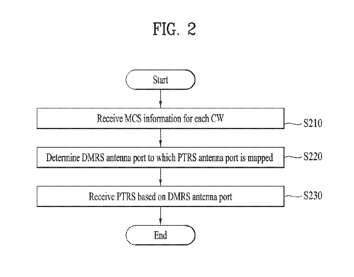
A method for operating a user equipment in a wireless communication is provided as an embodiment of the present invention. The method may include: receiving modulation and coding scheme (MCS) information for each of two or more codewords from a base station (BS); determining a demodulation reference signal (DMRS) antenna port to which a phase tracking reference signal (PTRS) antenna port is mapped based on the MCS information; and receiving a PTRS based on the DMRS antenna port, wherein a DMRS antenna port with the lowest index among one or more DMRS antenna ports included in a codeword with the highest MCS among the two or more codewords may be determined as the DMRS antenna port.

Description

CROSS-REFERENCE TO RELATED APPLICATIONS[0001]This application is the National Stage filing under 35 U.S.C. 371 of International Application No. PCT / KR2018 / 003455, filed on Mar. 23, 2018, which claims the benefit of U.S. Provisional Application No. 62 / 476,744, filed on Mar. 25, 2017, 62 / 520,666, filed on Jun. 16, 2017, 62 / 525,775, filed on Jun. 28, 2017, and 62 / 531,299, filed on Jul. 11, 2017, the contents of which are all hereby incorporated by reference herein in their entirety.TECHNICAL FIELD[0002]The present invention relates to a wireless communication system, and more particularly, to a method for receiving a phase tracking reference signal (PTRS) for phase noise cancellation in a system and apparatus therefor.BACKGROUND ART[0003]An ultra-high frequency radio communication system using mmWave is configured to operate at a center frequency in the range of several GHz to several tens of GHz. Due to such a center frequency feature, significant path loss may occur in a shadow area ...

Claims


Application Information

Patent Timeline
Patent Type & Authority Patents(United States)
IPC IPC(8): H04B1/10H04L1/00H04B7/04H04B7/0456H04L5/00H04B7/06
CPCH04L1/0003H04L1/0009H04L1/0026H04L5/0048H04L5/006H04L5/0091H04L5/0023H04L25/0224H04L27/266H04L27/2675H04L1/0047H04L5/005H04B7/0632H04L27/20H04W72/00H04B1/10H04B7/0473H04L5/00H04L1/00H04B7/06
Inventor LEE, KILBOMKANG, JIWONKIM, KIJUNKIM, KYUSEOKYUM, KUNIL
Owner LG ELECTRONICS INC
Why Eureka
Try Eureka