Airfoil for a gas turbine engine

a gas turbine engine and air filter technology, applied in the direction of machines/engines, stators, mechanical equipment, etc., can solve the problems of reducing service life or requiring additional maintenance, and achieve the effect of minimizing dust collection

Active Publication Date: 2019-10-22
GENERAL ELECTRIC CO
View PDF25 Cites 0 Cited by
  • Summary
  • Abstract
  • Description
  • Claims
  • Application Information

AI Technical Summary

Benefits of technology

[0005]In another aspect, embodiments of the invention relate to a method of minimizing dust collection in a gas turbine engine having an airfoil with a flow channel extending span-wise from a tip to a root and having a tip turn. The method includes flowing a cooling fluid over at least one fastback turbulator disposed at least partially within the tip turn.

Problems solved by technology

The cooling circuits can include one or more airflow element to enhance the cooling, however, such elements can lead to excessive collection of dust or particular matter reducing service life or requiring additional maintenance.

Method used


Image

  • Airfoil for a gas turbine engine
  • Airfoil for a gas turbine engine
  • Airfoil for a gas turbine engine

Examples


Embodiment Construction

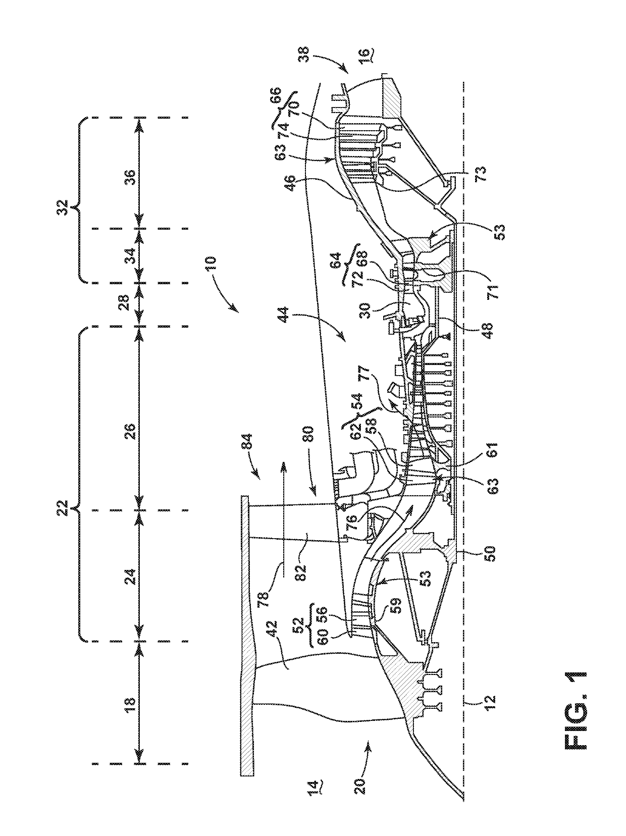
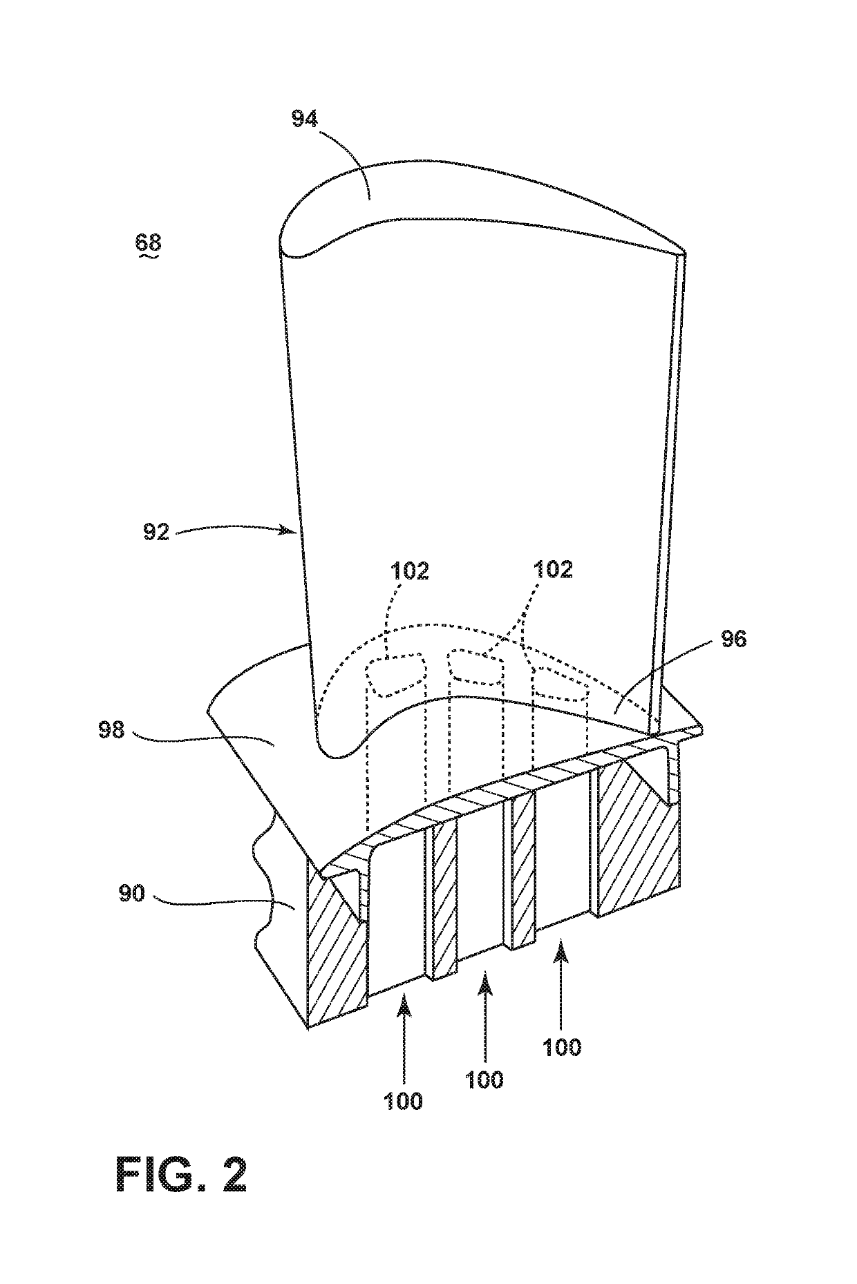
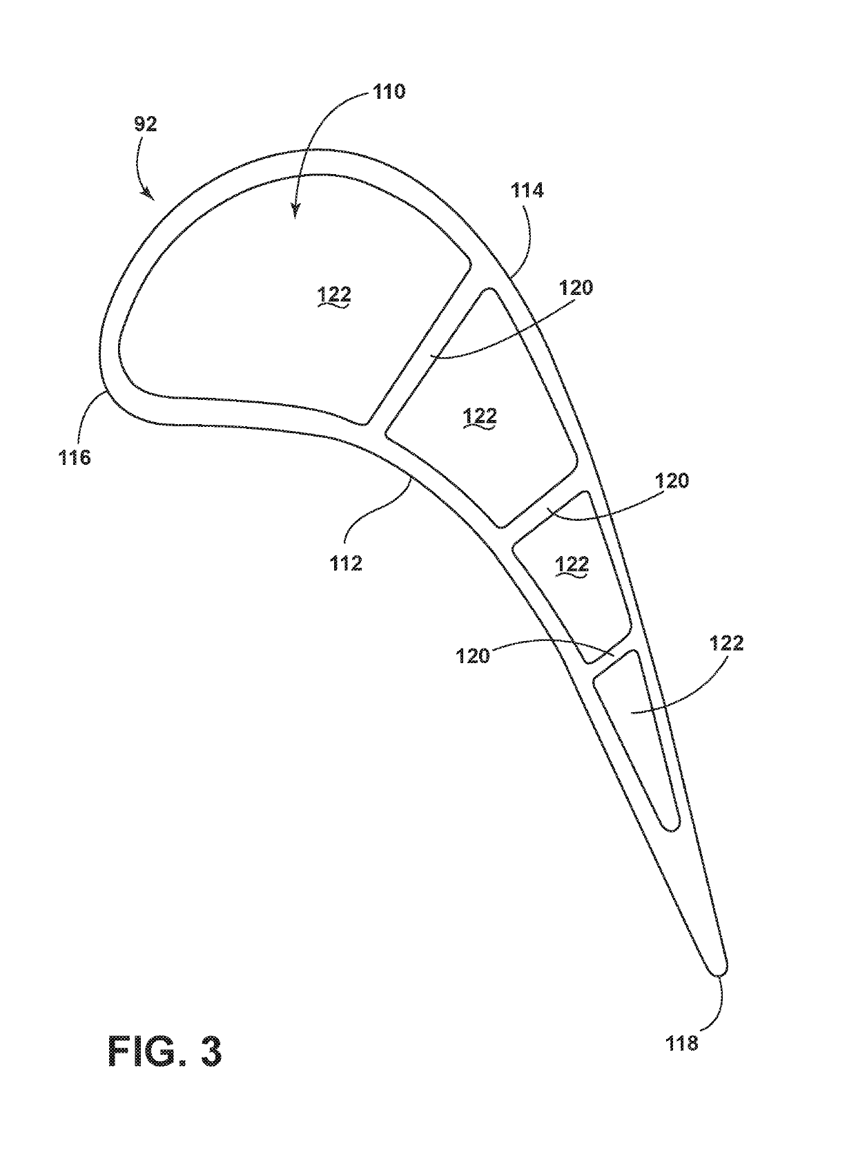
[0016]The described embodiments of the present invention are directed to an airfoil for a gas turbine engine having at least one fastback turbulator disposed at least partially within an internal tip turn. For purposes of illustration, the present invention will be described with respect to the turbine for an aircraft gas turbine engine. It will be understood, however, that the invention is not so limited and may have general applicability within an engine, including compressors, as well as in non-aircraft applications, such as other mobile applications and non-mobile industrial, commercial, and residential applications.

[0017]As used herein, the term “forward” or “upstream” refers to moving in a direction toward the engine inlet, or a component being relatively closer to the engine inlet as compared to another component. The term “aft” or “downstream” used in conjunction with “forward” or “upstream” refers to a direction toward the rear or outlet of the engine relative to the engine...


PUM


Abstract

A method and apparatus for an airfoil in a gas turbine engine can include an outer surface bounding an interior. At least one flow channel can be defined among one or more full-length and partial-length ribs to further define a cooling circuit within the airfoil. The cooling circuit can have at least one tip turn at the partial-length rib, having at least on fastback turbulator disposed at least partially within the tip turn.

Description

BACKGROUND OF THE INVENTION[0001]Turbine engines, and particularly gas or combustion turbine engines, are rotary engines that extract energy from a flow of combusted gases passing through the engine onto a multitude of rotating turbine blades.[0002]Gas turbine engines for aircraft are designed to operate at high temperatures to maximize engine efficiency, so cooling of certain engine components, such as the high pressure turbine and the low pressure turbine, can be beneficial. Typically, cooling is accomplished by ducting cooler air from the high and / or low pressure compressors to the engine components that require cooling. Temperatures in the high pressure turbine are around 1000° C. to 2000° C. and the cooling air from the compressor is around 500° C. to 700° C. While the compressor air is a high temperature, it is cooler relative to the turbine air, and can be used to cool the turbine.[0003]Contemporary turbine blades generally include one or more interior cooling circuits for ro...

Claims


Application Information

Patent Timeline
Patent Type & Authority Patents(United States)
IPC IPC(8): F01D5/18F01D25/12F01D9/04
CPCF01D5/188F01D9/041F01D25/12F01D5/187F05D2260/2212F05D2240/12F05D2220/32F05D2260/607F05D2240/30Y02T50/676F05D2250/185F01D5/141F01D5/189F02C6/20Y02T50/60
Inventor BUNKER, RONALD SCOTTBRIGGS, ROBERT DAVIDALLEN, JASON RANDOLPHFELDMANN, KEVIN ROBERT
Owner GENERAL ELECTRIC CO
Why Eureka
Try Eureka