Transceiver apparatus and method having ethernet-over-power and power-over-ethernet capability

a technology of ethernet overpower and power overethernet, applied in the direction of power supply arrangement, line transmission details, powerline communications applications, etc., can solve the problem of limited interoperability of devices of separate and independent standards, and achieve the effect of simplifying the ability to network and enhancing the reach of ethernet networking

Inactive Publication Date: 2010-02-09
ABOUNDI
View PDF34 Cites 23 Cited by
  • Summary
  • Abstract
  • Description
  • Claims
  • Application Information

AI Technical Summary

Benefits of technology

[0010]According to another aspect, the device may include an enclosure that encloses the power line modem and the power circuit. In an embodiment, the enclosure may include a top surface, a bottom surface, and at least two side surfaces, the bottom surface having at least one ventilation slot for in flow, the side surfaces having at least one ventilation slot for in flow and at least one ventilation slot for out flow. The ventilation slots of the side surfaces may be recessed for improved convection air flow cooling and to minimize dust collection in the device.
[0012]An advantage that the invention provides is the convergence of two totally distinctive types of Ethernet applications into a single device which can further enhance the reach of Ethernet networking by drastically simplifying the ability to network various types of equipment that may have differing powering and connectivity needs. Hence, embodiments of the invention can provide for home networking with “smart” appliances being networked seamlessly and efficiently.

Problems solved by technology

However, such interoperability is limited to the devices of the separate and independent standards.

Method used


Image

  • Transceiver apparatus and method having ethernet-over-power and power-over-ethernet capability
  • Transceiver apparatus and method having ethernet-over-power and power-over-ethernet capability
  • Transceiver apparatus and method having ethernet-over-power and power-over-ethernet capability

Examples


Embodiment Construction

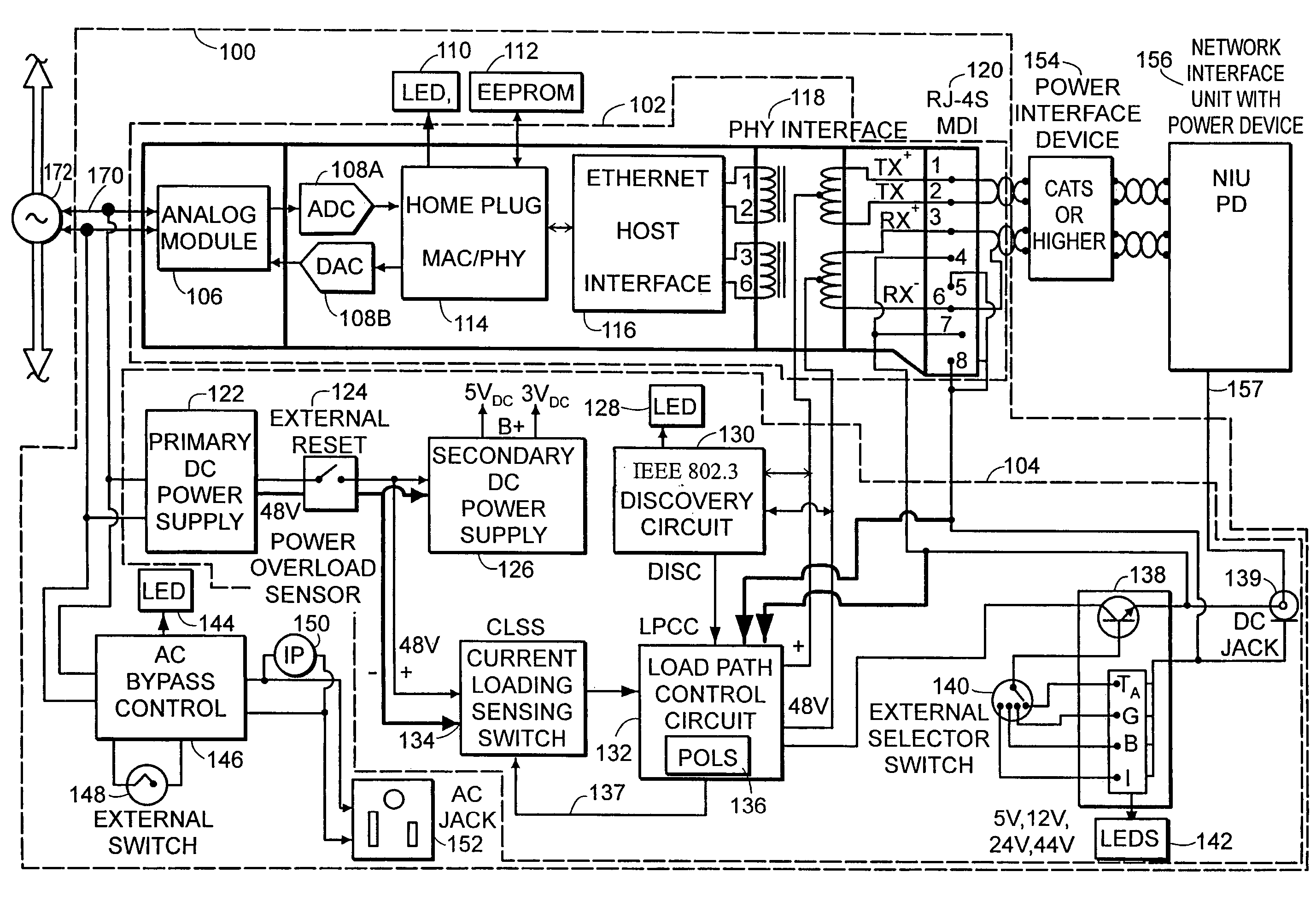
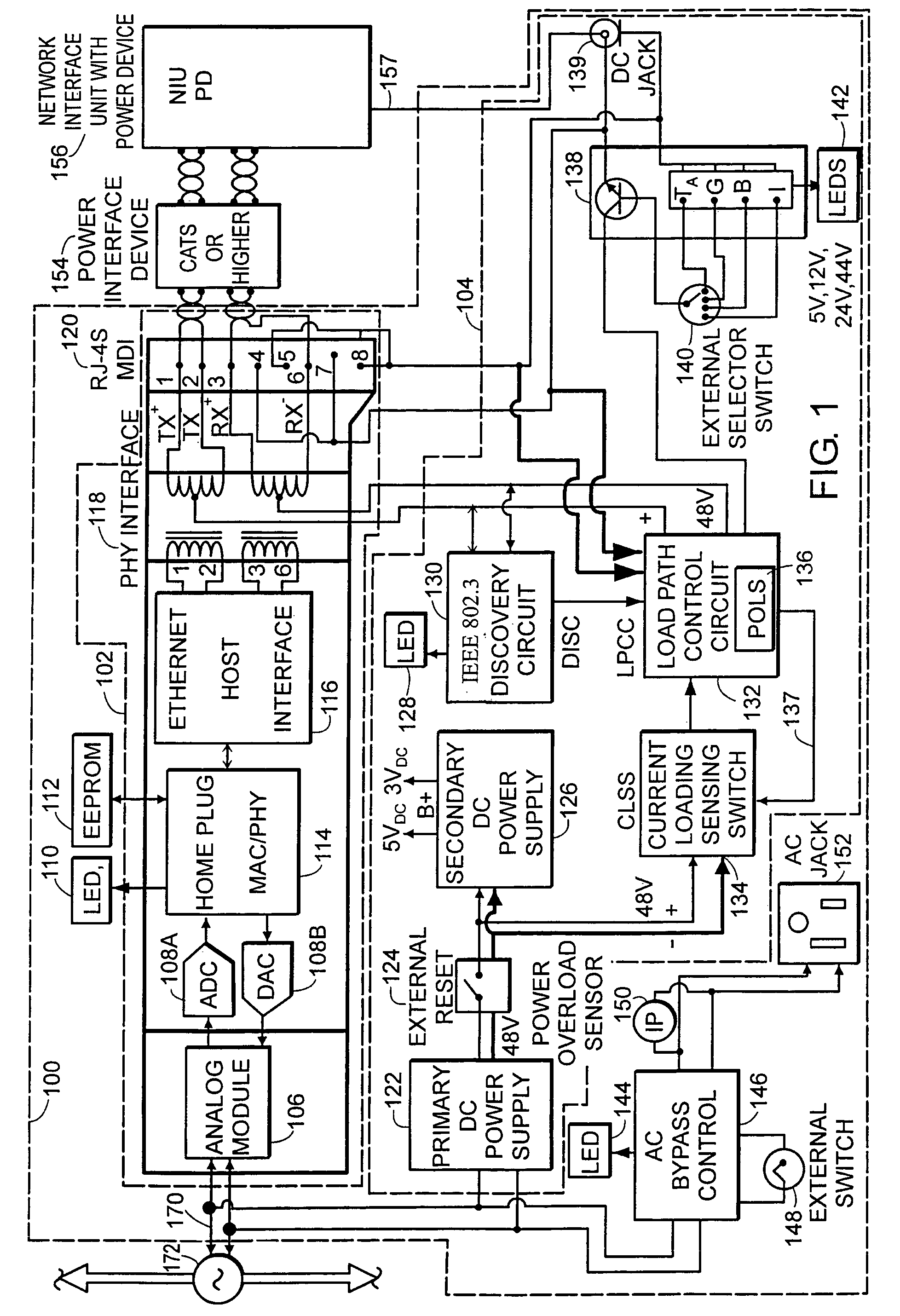
[0019]FIG. 1 is a block diagram that illustrates principles of the present invention. A transceiver device 100 is shown coupled between power line 172 and network interface unit (NIU) 156. The device 100 is connected to power line 172 through AC plug 170. The power line 172 is generally configured to provide home distribution wiring for carrying AC power and data signals, preferably according to the standard for Ethernet over Power (EoP) as specified by the HomePlug Powerline Alliance. The device is connected to the NIU 156 over a power interface device 154 (e.g., Category 5, 5E or higher grade cabling).

[0020]The device 100 includes a power line modem 102 and a power circuit 104. Generally, the power circuit 104 is configured to couple a DC power signal to the power line modem 102 for delivery to the NIU 156.

[0021]The power line modem 102 includes an analog module 106; analog-to-digital converter (ADC) 108A and digital-to-analog converter (DAC) 108B; a HomePlug MAC / PHY device 114; a...


PUM


Abstract

A transceiver device for coupling between a power line and a network interface unit includes a power line modem for transmitting and receiving data between the power line and the network interface unit and a power circuit coupled to the power line modem that is adapted to deliver a DC power signal to the network interface unit. The power circuit includes a discovery circuit adapted to determine the type of network interface unit that is attached. A load path control circuit switches the DC power signal between a PHY interface and a connector interface of the power line modem based on the determined type.

Description

BACKGROUND OF THE INVENTION[0001]As usage of the Internet expands, more and more people are purchasing multiple Personal Computers (PCs) for use by family members in the home. These multiple PCs can be “networked” together in the home to share and access common resources such as printers, files and Internet access (e.g., xDSL and cable modems). One well-known technology which has assisted in fueling the growth of networking is deployment of Local Area Networks (LAN) based on Ethernet (covered under several standards referred to generally as IEEE 802.3x), which has become the “default” LAN infrastructure standard.[0002]At present, there are several types of the existing ubiquitous Ethernet technology that may be used in certain home networking applications, with each having its own standard to assure interoperability among various equipment vendors. A first type is the Power Line Communications (PLC) application that utilizes so-called Ethernet over Power (EoP) under the HomePlug sta...

Claims


Application Information

Patent Timeline
Patent Type & Authority Patents(United States)
IPC IPC(8): H04B1/38H04B3/44H04B3/54H04L12/46
CPCH04B3/44H04B3/54H04L12/46H04B2203/5445H04B2203/5454H04B2203/5408
Inventor YU, HONG
Owner ABOUNDI
Why Eureka
Try Eureka