Wood cutting band saw blade

a band saw blade and band saw technology, applied in the field of saw blades, can solve the problems of excessive saw dust remaining on wood products, such as pallets, dust can be particularly problematic, freeze, and the side walls of the blades are hardened, so as to achieve the effect of reducing the collection of dus

Inactive Publication Date: 2012-02-14
BLACK & DECKER INC
View PDF36 Cites 48 Cited by
  • Summary
  • Abstract
  • Description
  • Claims
  • Application Information

AI Technical Summary

Benefits of technology

[0010]One advantage of the present invention is that the location of the shelf or like means for reducing the quantity of dust passing through the dust gap minimizes the collection of dust on both the kerf walls and sides of the saw blade.
[0011]Other advantages of the present invention will become readily apparent in view of the following detailed description of preferred embodiments and accompanying drawings.

Problems solved by technology

For example, excessive saw dust remaining on wood products, such as pallets, will tend to collect in the eyes and / or breathing passages of workers handling the pallets.
In addition, dust can be particularly problematic when cutting frozen wood, such as logs.
Then, the glue-like mixture freezes when the blade exits the work piece, resulting in a frozen, hardened layer of saw dust on the side walls of the blade.
The frozen layer of sawdust can cause unwanted vibrations in the saw blade, and if sufficiently thick, can cause the blade to fracture.
Instead, saw dust passes by either side of the projections in the direction of the kerf walls thereby building up and causing the above-described problems.

Method used


Image

  • Wood cutting band saw blade
  • Wood cutting band saw blade
  • Wood cutting band saw blade

Examples


Embodiment Construction

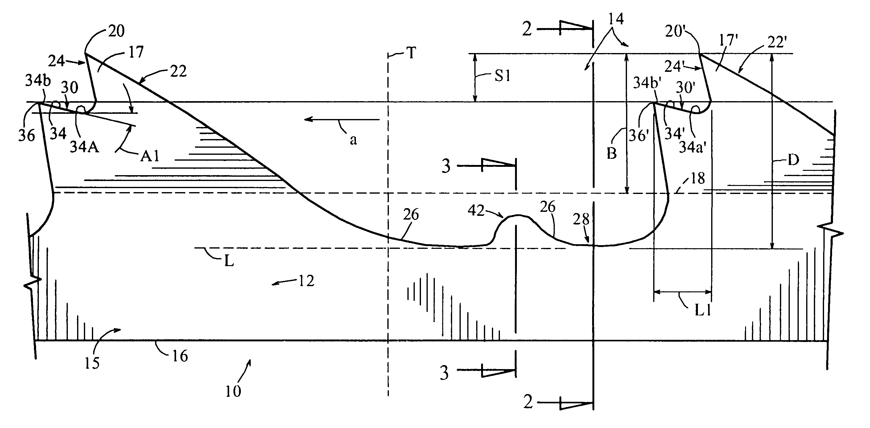
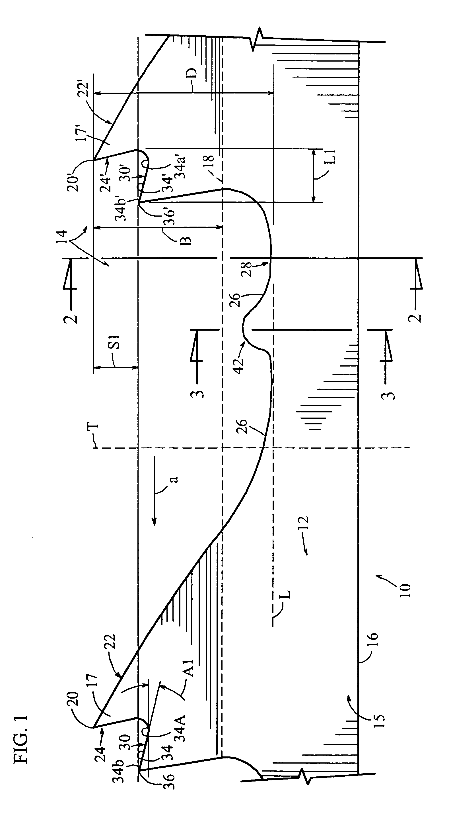
[0019]A wood cutting band saw blade in accordance with an embodiment of the present invention is illustrated generally at 10 in FIG. 1. The band saw blade 10 defines a cutting direction indicated by the arrow a, and comprises a band 12 having cutting edge 14 and a base 15 including a back edge 16. The band saw blade 10 defines a longitudinal axis “L” and a transverse axis “T”. It will be appreciated by those of ordinary skill in the relevant art that the cutting edge 14 of the band saw blade 10 comprises a plurality of teeth 17, 17′, 17″(FIG. 2) etc., disposed along the cutting edge. It will also be appreciated that all or a subset of the teeth 17, 17′, 17″, etc. may be angled or set along a bend plane 18 as better seen in FIG. 2.

[0020]Referring now to FIG. 2, a plurality of the teeth 17′, 17″, etc. are each set at an angle A′, A″, etc. relative to axis A. In the preferred embodiments of the present invention, angle A′, A″, etc. as preferably within a range of approximately 75-89°, ...


PUM

PropertyMeasurementUnit
heightaaaaaaaaaa
widthaaaaaaaaaa
widthaaaaaaaaaa

Abstract

A wood cutting band saw blade includes a cutting edge and a back edge, wherein the cutting edge is defined by a plurality of teeth spaced relative to each other. The plurality of teeth include a plurality of set teeth each having a tip, each defining a bend plane, and each including a shelf located at least partially between the tip and the bend plane for reducing saw dust passing to the kerf and accumulating on the band saw blade. Each of the set teeth may define a relief surface and a cutting surface where the relief surface extends from one side of the tip in a direction opposite that of the movement of the band saw blade and the cutting surface extends from another side of the tip. The shelf includes a shelf surface extending from the cutting surface and may terminate in a shelf tip.

Description

FIELD OF THE INVENTION[0001]The present invention relates generally to saw blades and, more particularly, to wood cutting band saw blades having a tooth form configured to reduce saw dust passing to the kerf walls and to the side walls of the band saw blade.BACKGROUND INFORMATION[0002]It is desirable to minimize the amount of sawdust remaining on the kerf walls when cutting work pieces. For example, excessive saw dust remaining on wood products, such as pallets, will tend to collect in the eyes and / or breathing passages of workers handling the pallets. In addition, dust can be particularly problematic when cutting frozen wood, such as logs. In particular, the fast-moving blade creates friction that, in turn, heats the wood and allows the wood to release moisture. The moisture collects on the kerf walls and sides of the band saw blade, and binds the sawdust thereon into a glue-like mixture. Then, the glue-like mixture freezes when the blade exits the work piece, resulting in a frozen...

Claims


Application Information

Patent Timeline
Patent Type & Authority Patents(United States)
IPC IPC(8): B27B33/06B23D61/12B27B33/02
CPCB23D61/121Y10T83/935Y10T83/9319Y10T83/9358Y10T83/9317
Inventor CRANNA, MARK T.MILLER, DARRIEL
Owner BLACK & DECKER INC
Why Eureka
Try Eureka