Component cooling for a gas turbine engine

a gas turbine engine and component cooling technology, applied in the direction of machines/engines, efficient propulsion technologies, lighting and heating apparatus, etc., can solve the problem of dust accumulation along the engine component lin

Inactive Publication Date: 2017-08-17
GENERAL ELECTRIC CO
View PDF4 Cites 2 Cited by
  • Summary
  • Abstract
  • Description
  • Claims
  • Application Information

AI Technical Summary

Problems solved by technology

The concavities tend to generate an unsteady or vortical airflow as the cooling flow passes through or over them, which can lead to reduction of dust build-up along the engine component.

Method used


Image

  • Component cooling for a gas turbine engine
  • Component cooling for a gas turbine engine
  • Component cooling for a gas turbine engine

Examples


Embodiment Construction

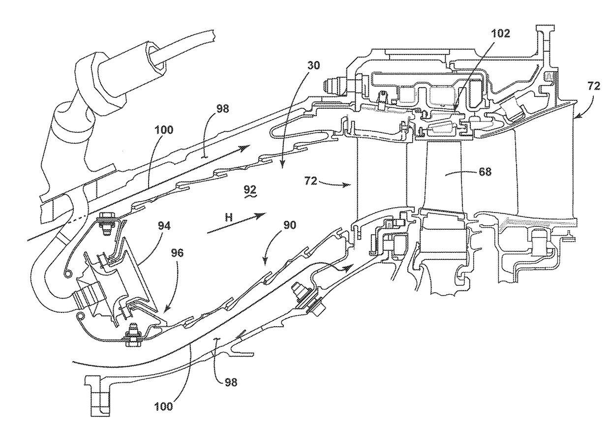
[0016]The described embodiments of the present invention are directed to a dimple disposed on a cooling surface of a component of a gas turbine engine. For purposes of illustration, the present invention will be described with respect to the turbine for an aircraft gas turbine engine. It will be understood, however, that the invention is not so limited and may have general applicability within an engine, including compressors, as well as in non-aircraft applications, such as other mobile applications and non-mobile industrial, commercial, and residential applications.

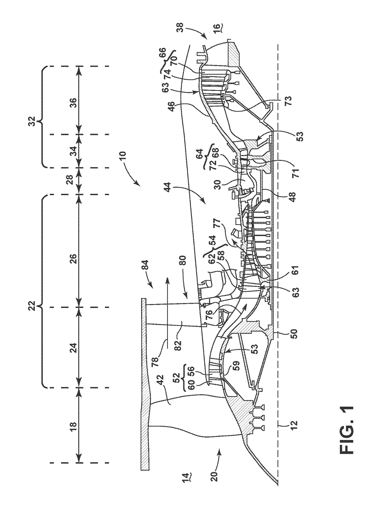
[0017]As used herein, the term “forward” or “upstream” refers to moving in a direction toward the engine inlet, or a component being relatively closer to the engine inlet as compared to another component. The term “aft” or “downstream” used in conjunction with “forward” or “upstream” refers to a direction toward the rear or outlet of the engine relative to the engine centerline. “Upstream” as used herein also refers to ...


PUM


Abstract

An apparatus and method for an engine component having a hot surface adjacent a hot combustion gas flow and a cooling surface adjacent a cooling fluid flow can include at least one dimple for enhancing the cooling along the cooling surface. The dimple can be shaped having a head and a tail with the head disposed upstream of the tail to provide for reduced dust collection along the engine component.

Description

BACKGROUND OF THE INVENTION[0001]Turbine engines, and particularly gas or combustion turbine engines, are rotary engines that extract energy from a flow of combusted gases passing through the engine in a series of compressor stages, which include pairs of rotating blades and stationary vanes, through a combustor, and then onto a multitude of turbine blades.[0002]Gas turbine engines for aircraft are designed to operate at high temperatures to maximize engine efficiency, so cooling of certain engine components, such as the high pressure turbine and the low pressure turbine, can be necessary. Typically, cooling is accomplished by ducting cooler air from the high and / or low pressure compressors to the engine components that require cooling. Temperatures in the high pressure turbine are around 1000° C. to 2000° C. and the cooling air from the compressor is around 500° C. to 700° C. While the compressor air is a high temperature, it is cooler relative to the turbine air, and can be used t...

Claims


Application Information

Patent Timeline
Patent Type & Authority Applications(United States)
IPC IPC(8): F02C7/141F23R3/16F23R3/00
CPCF02C7/141F23R3/16F23R3/005F02C7/14F05D2250/28F01D5/187F15D1/005F05D2250/232F05D2250/61F05D2260/2212F05D2260/607F05D2250/241F16K1/00Y02T50/60
Inventor BUNKER, RONALD SCOTTBAILEY, JEREMY CLYDE
Owner GENERAL ELECTRIC CO
Why Eureka
Try Eureka