Unitary filter cartridge

a filter cartridge and unitary technology, applied in the field of industrial baghouses, can solve the problems of increasing industrial emissions regulatory controls, difficult installation and removal of filter cartridges of this type, and difficult installation and maintenance of filter cartridges, so as to maintain the flexibility of the upper sleeve and minimize the collection of dust.

Inactive Publication Date: 2001-05-08
BHA ALTAIR
View PDF42 Cites 26 Cited by
  • Summary
  • Abstract
  • Description
  • Claims
  • Application Information

AI Technical Summary

Benefits of technology

A filter cartridge according to the present invention is provided having a unitary structure with a pleat pack formed securely about a tubular interior screen. Opposite ends of the pleat pack and interior screen are integrally formed within a bottom end cap and an upper or top sleeve. The bottom end cap is constructed to follow the contour of the pleat pack to minimize the collection of dust about the bottom perimeter thereof. The upper sleeve is formed of a flexible material which may be manually deformed to pass through an opening in a tube sheet which retains the filter cartridge. The interior screen ends below the upper end of the sleeve to maintain the flexibility of the upper sleeve. The top sleeve comprises a lower lip extending along the interior of the inner screen to securely engage the inner screen. The lower lip is formed integrally with a radially extending ledge which is formed with an upwardly projecting funnel shaped side wall. The side wall includes an inner grove at its upper end which extends about a perimeter of the top sleeve. A supporting ledge is formed upon the upper end of the side wall and projects radially outward about a perimeter of the filter cartridge. The supporting ledge need not be continuous, so long as it is capable of supporting the filter cartridge.

Problems solved by technology

Continuous emphasis on environmental quality has resulted in increasingly strenuous regulatory controls on industrial emissions.
The installation and maintenance of filter cartridges of this type has traditionally been a time consuming and costly operation.
Hence, this filter cartridge is quite difficult to install and remove.
However, the systems proposed heretofore have experienced disadvantages.
In particular, the filter cartridges of the '116 patent and '168 publication require unduly complex structures having multiple parts which must be assembled before the cartridges are inserted.
Such assembly is extremely difficult.
This alignment is extremely difficult.
This operation undesirably complicates the filter changing process.
The cartridge of the '757 patent requires an overly complex manufacturing process.
The separate securing means increase the number of parts and necessitate unduly complex installation and removal processes.

Method used


Image

  • Unitary filter cartridge
  • Unitary filter cartridge

Examples


Embodiment Construction

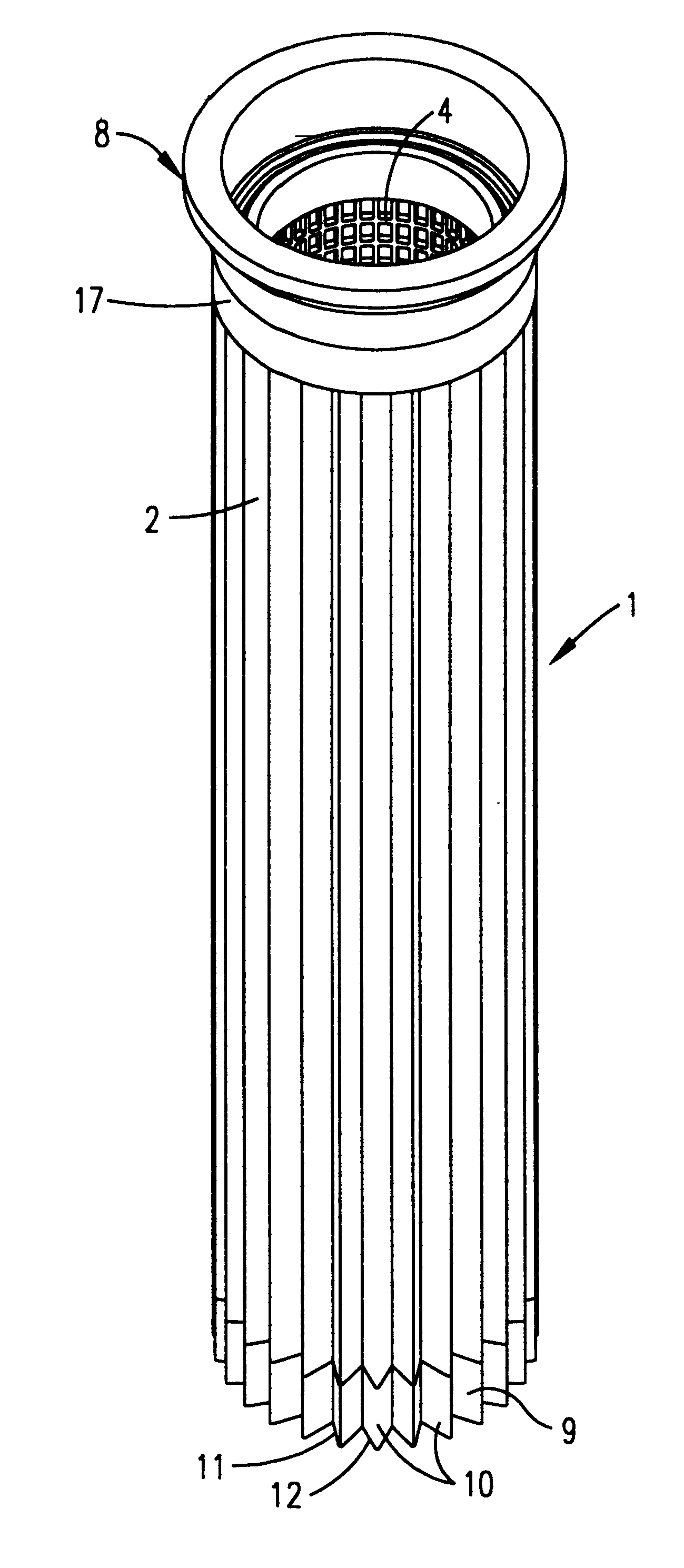
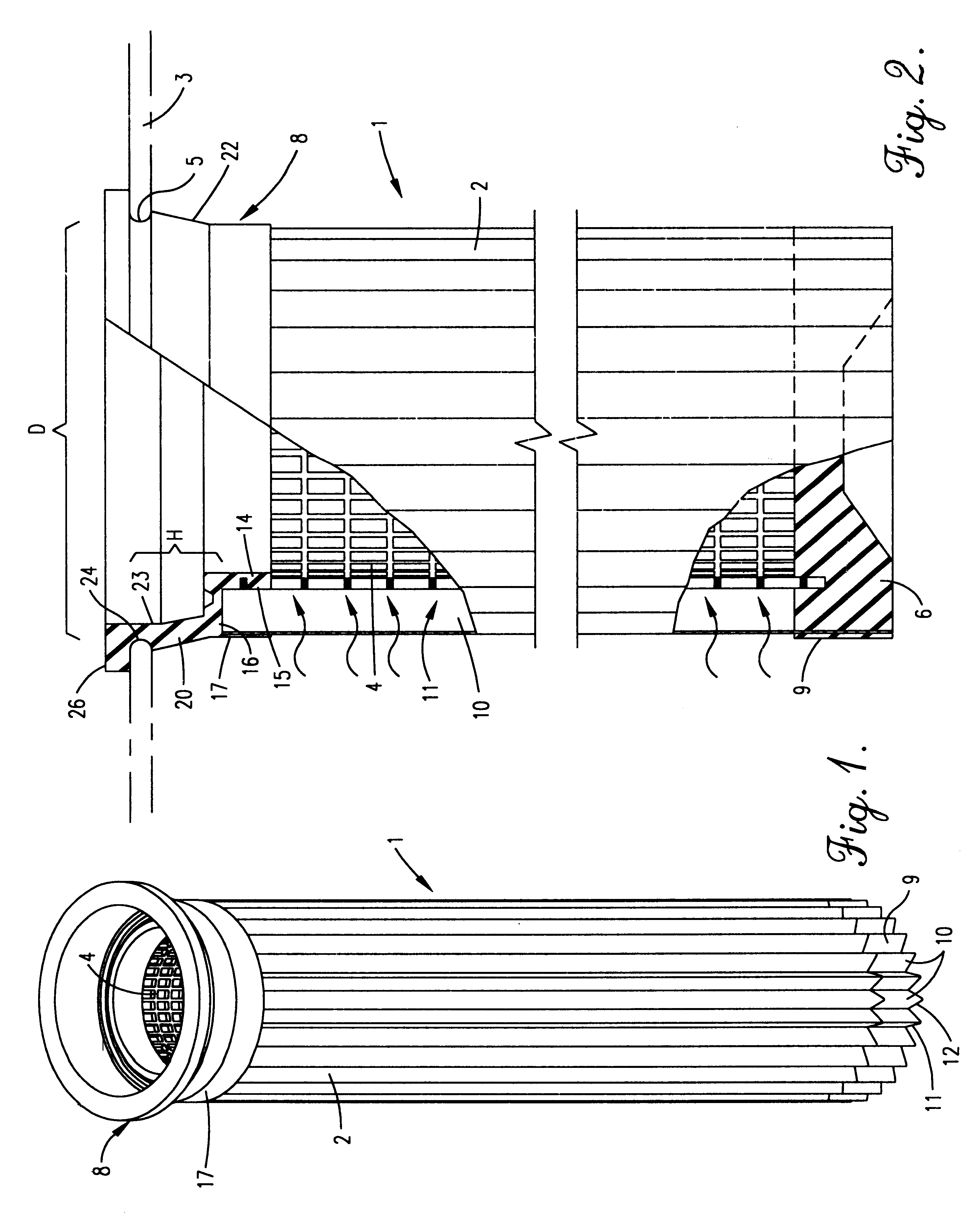
FIG. 1 generally illustrates a filtered cartridge according to the present invention as designated by the reference numeral 1. The filter cartridge 1 is received within a tube sheet 3 having an opening 5 therethrough with a diameter D. The cartridge 1 filters particulate material from air or liquid as the air or liquid passes radially inward through the cartridge 1 and upward through the opening 5. The filter cartridge 1 includes a pleat pack 2 (also referred to as a filter sheet or filter medium) formed in a substantially tubular shape about a filtered chamber with accordion folds about a perimeter thereof. The pleat pack 2 may be constructed of any conventionally known filtering medium. Each fold is constructed with outer filter walls 10 extending along the length of the cartridge 1. Adjoining filter walls 10 form internal and external V-shaped voids 11 and 12.

The pleat pack is formed about, and abuts firmly against, a tubular inner screen 4 having a rectangular mesh pattern there...


PUM

PropertyMeasurementUnit
flexibleaaaaaaaaaa
diameteraaaaaaaaaa
outer diameteraaaaaaaaaa

Abstract

A filter cartridge according to the present invention is provided having a unitary structure with a pleat pack formed securely about an interior screen. Opposite ends of the pleat pack and interior screen are integrally formed within a bottom end cap and an upper sleeve. The bottom end cap is constructed to follow the couture of the pleat pack to minimize the collection of dust about the bottom perimeter thereof. The upper sleeve is formed of a flexible material which may be manually deformed to pass through an opening in a tube sheet which retains the filter cartridge. The top sleeve comprises a lower lip extending along the interior of the inner screen to securely engage the inner screen. The lower lip is formed integrally with a radially extending ledge which is formed with an upwardly projecting funnel shaped side wall. The side wall includes an inner grove at its upper end which extends about a perimeter of the top sleeve. A supporting ledge is formed upon the upper end of the side wall and projects radially outward about a perimeter of the filter cartridge. The supporting ledge need not be continuous, so long as it is capable of supporting the filter cartridge.

Description

FIELD OF THE INVENTIONThe present invention generally relates to industrial baghouses and more particularly to an air filter cartridge for removing particles or dust from a stream of air moving through the baghouse.BACKGROUND OF THE INVENTIONThis invention relates to industrial baghouses and more particularly, to a tensioning device for connecting cylindrical bag filters to an overhead support.Continuous emphasis on environmental quality has resulted in increasingly strenuous regulatory controls on industrial emissions. One technique which has proven highly effective in controlling air pollution has been separation of undesirable particulate matter from a gas stream by fabric filtration. Such filtration is carried out in dust collection apparatus known in the trade as a "baghouse" which operates on the same general principle as an ordinary household vacuum cleaner, except on a much larger scale. Basically, the baghouse is a sheet metal housing divided into two chambers, referred to ...

Claims


Application Information

Patent Timeline
Patent Type & Authority Patents(United States)
IPC IPC(8): B01D46/24B01D46/52B01D46/00
CPCB01D46/0005B01D46/2411B01D46/521B01D2265/06B01D2271/02
Inventor OUSSOREN, REINOUT G.CLEMENTS, JACK T.
Owner BHA ALTAIR
Why Eureka
Try Eureka