
Multi-pole dome switch

a multi-pole, dome switch technology, applied in the direction of emergency contacts, switch side locations, convex contact surfaces, etc., can solve the problems of increasing the bulk of the electronic device, unable to activate two separate electronic devices by pressing a single switch, and the bulk of the dpdt switch is too large for many applications

Active Publication Date: 2019-10-29
ZIMMER TRENT
View PDF6 Cites 3 Cited by
  • Summary
  • Abstract
  • Description
  • Claims
  • Application Information

AI Technical Summary

Benefits of technology

The patent describes a multi-pole dome switch that uses a tactile metal dome and conductive insert separated by an insulator to prevent short circuits. The switch has a curved contact portion that makes conductive contact with a circuit on a printed circuit board (PCB) when the dome is pressed. The switch also has a centrally located bore that allows for conductive connection with another circuit on the PCB. The insulator has a larger diameter annular flange than the conductive insert to prevent short circuits. The switch is assembled with a non-conductive tape and the dome protrusions ensure conductive contact with two traces when pressed. The technical effects of this design are reliable and reliable performance of the switch, improved manufacturing efficiency, and reduced risk of short circuits.

Problems solved by technology

However, using two dome switches to independently close two separate circuits has several disadvantages.
First, the overall bulk of an electronic device increases as the number of dome switches increases.
Second, since two prior art dome switches cannot be co-mounted, actuating two separate electronic devices by depressing a single switch is not possible.
Unfortunately, DPDT switches are too bulky for many applications.

Method used


Image

  • Multi-pole dome switch
  • Multi-pole dome switch
  • Multi-pole dome switch

Examples


Embodiment Construction

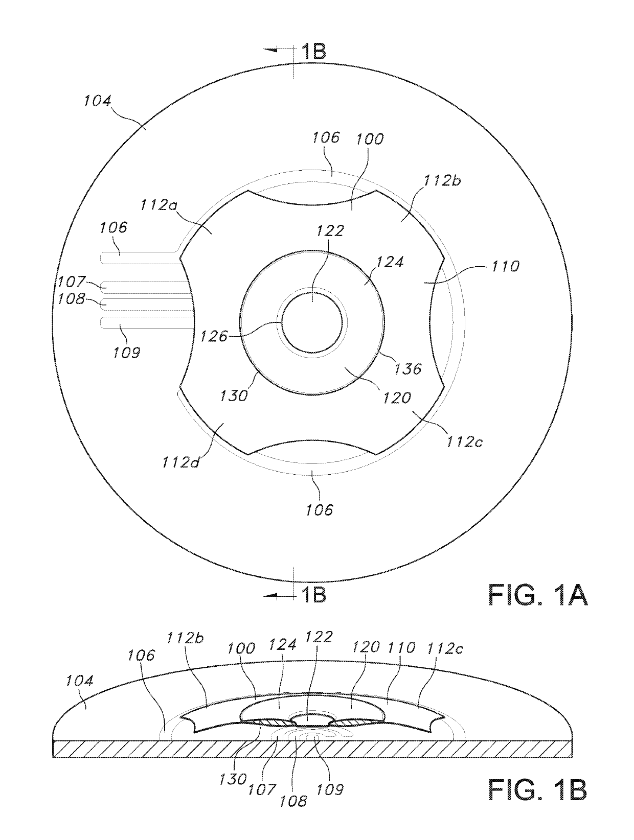
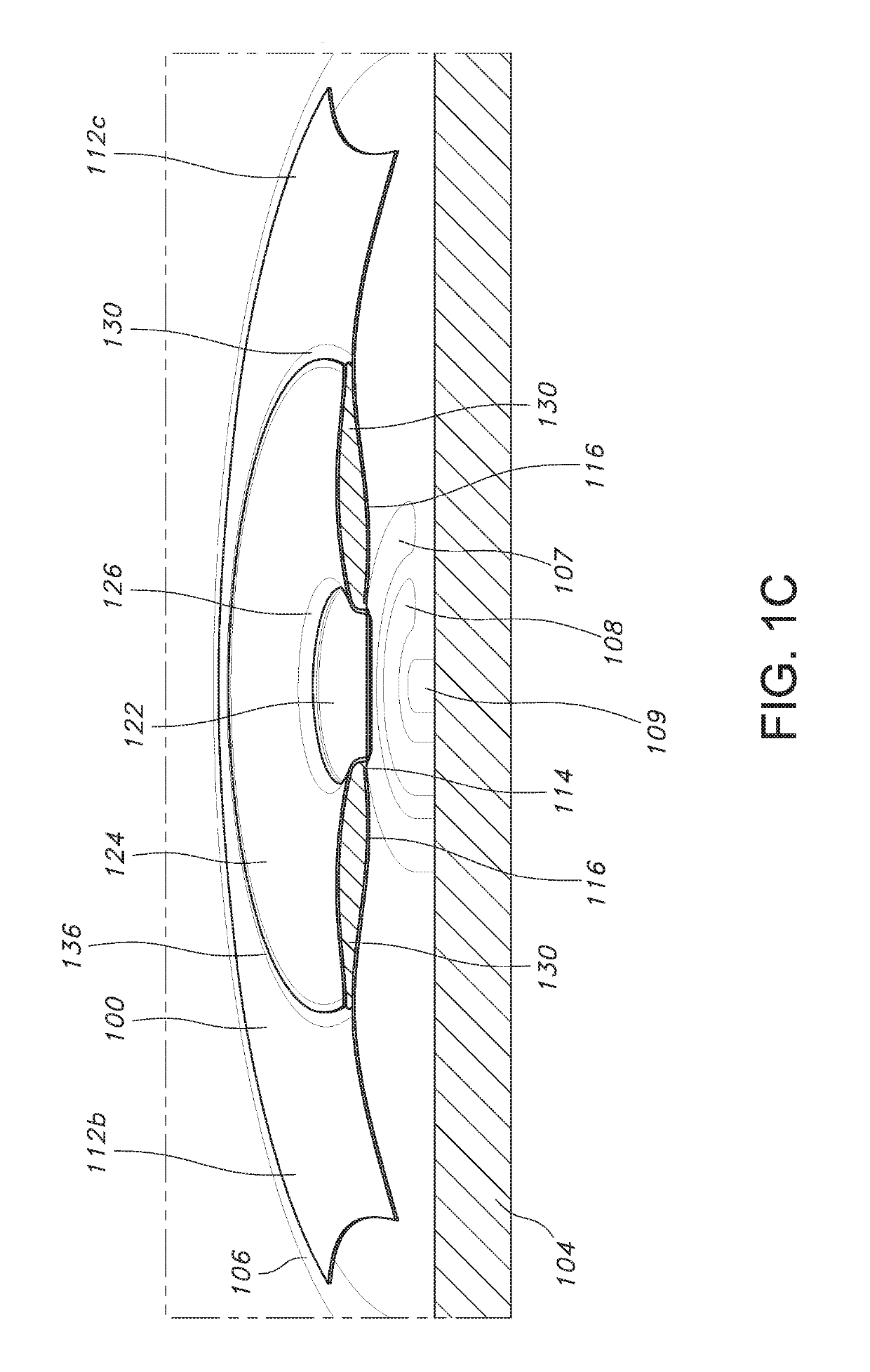
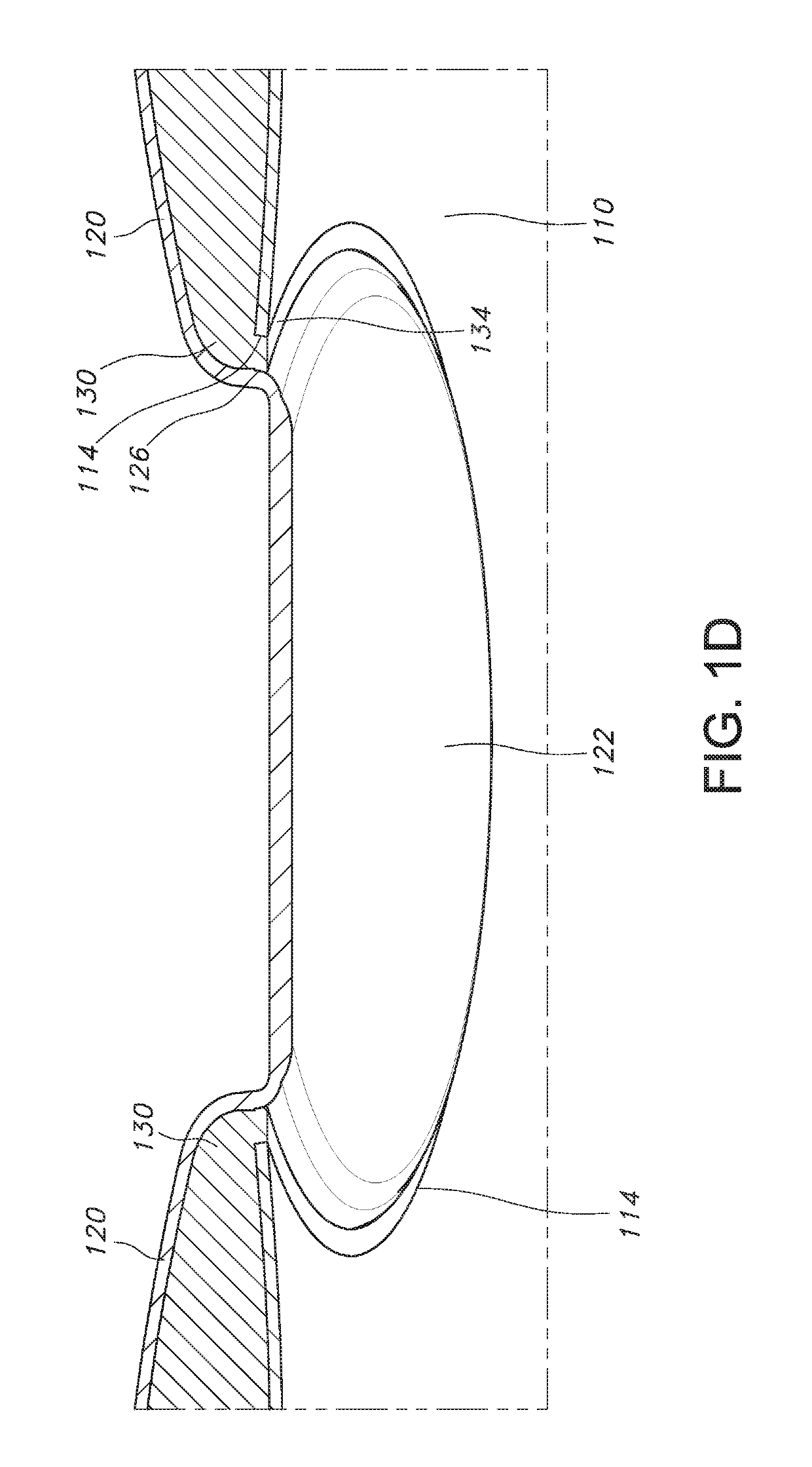
[0031]FIGS. 1A-1D illustrate an example multi-pole dome switch 100 according to the principles of the present disclosure. In some implementations, a single multi-pole dome switch 100 may be configured to simultaneously, or nearly simultaneously, close or open two circuits. In this way, for example, two separate electrical devices may be simultaneously, or nearly simultaneously, turned on or off.

[0032]As shown in FIGS. 1A and 1B, in some implementations, a multi-pole dome switch 100 may be disposed upon a printed circuit board (PCB) 104. In some implementations, the PCB 104 may include a first trace 106, a second trace 107, a third trace 108, and a fourth trace 109. In some implementations, the first trace 106 and the second trace 107 may be portions of a first open circuit; the third trace 108 and the fourth trace 109 may be portions of a second open circuit.

[0033]As shown in FIGS. 1A and 1B, in some implementations, a multi-pole dome switch 100 may comprise a tactile metal dome 110...


PUM


Abstract

Implementations of a multi-pole dome switch configured to simultaneously, or nearly simultaneously, close or open two separate circuits are provided. In some implementations, a multi-pole dome switch may comprise a tactile metal dome and a conductive insert that are separated by an insulator. In some implementations, when the dome is depressed, the dome and the conductive insert are configured to simultaneously, or nearly simultaneously, make conductive contact with two traces of a first circuit and two traces of a second circuit, respectively, positioned thereunder on a PCB. In this way, the multi-pole dome switch is able to simultaneously, or nearly simultaneously, close two separate circuits. Succinctly put, in some implementations, the multi-pole dome switch may be configured to act as a double-pole, double-throw switch.

Description

CROSS REFERENCE TO RELATED APPLICATION[0001]This application claims the benefit of U.S. Provisional Application Ser. No. 62 / 519,111, which was filed on Jun. 13, 2017, and is incorporated herein by reference in its entirety.TECHNICAL FIELD[0002]This disclosure relates to implementations of a multi-pole dome switch.BACKGROUND[0003]A dome switch, or dome, configured to be mounted on a printed circuit board (PCB), a flex circuit, or a membrane is well known in the prior art. Each dome switch may be secured to a mounting substrate (e.g., a PCB) by an adhesive. To increase the actuation force of a single switch, two domes may be stacked in a single position on the mounting substrate. When depressed, a dome switch may be configured to make contact with two traces and thereby close (or complete) a single circuit. Therefore, two dome switches would be required to close two separate circuits.[0004]However, using two dome switches to independently close two separate circuits has several disadv...

Claims


Application Information

Patent Timeline
Patent Type & Authority Patents(United States)
IPC IPC(8): H01H13/64H01H13/52H01H13/14H01H13/803
CPCH01H13/64H01H13/52H01H13/14H01H2203/038H01H13/803H01H2215/024H01H2211/036H01H2215/016H01H2215/018H01H2225/006H01H2225/01H01H2227/022H01H2215/01H01H2205/004H01H2203/024H01H2227/0261
Inventor ZIMMER, TRENT
Owner ZIMMER TRENT
Learn More