Method for processing material to be rolled on a rolling line, and rolling line

a technology of rolling line and rolling line, which is applied in the direction of rolling speed control device, tension/compression control device, metal-working apparatus, etc., can solve the problems of wire or loop breakage, tension or compression load, and the approach of very time-consuming and costly

Active Publication Date: 2019-12-10
PRIMETALS TECH GERMANY
View PDF20 Cites 0 Cited by
  • Summary
  • Abstract
  • Description
  • Claims
  • Application Information

AI Technical Summary

Benefits of technology

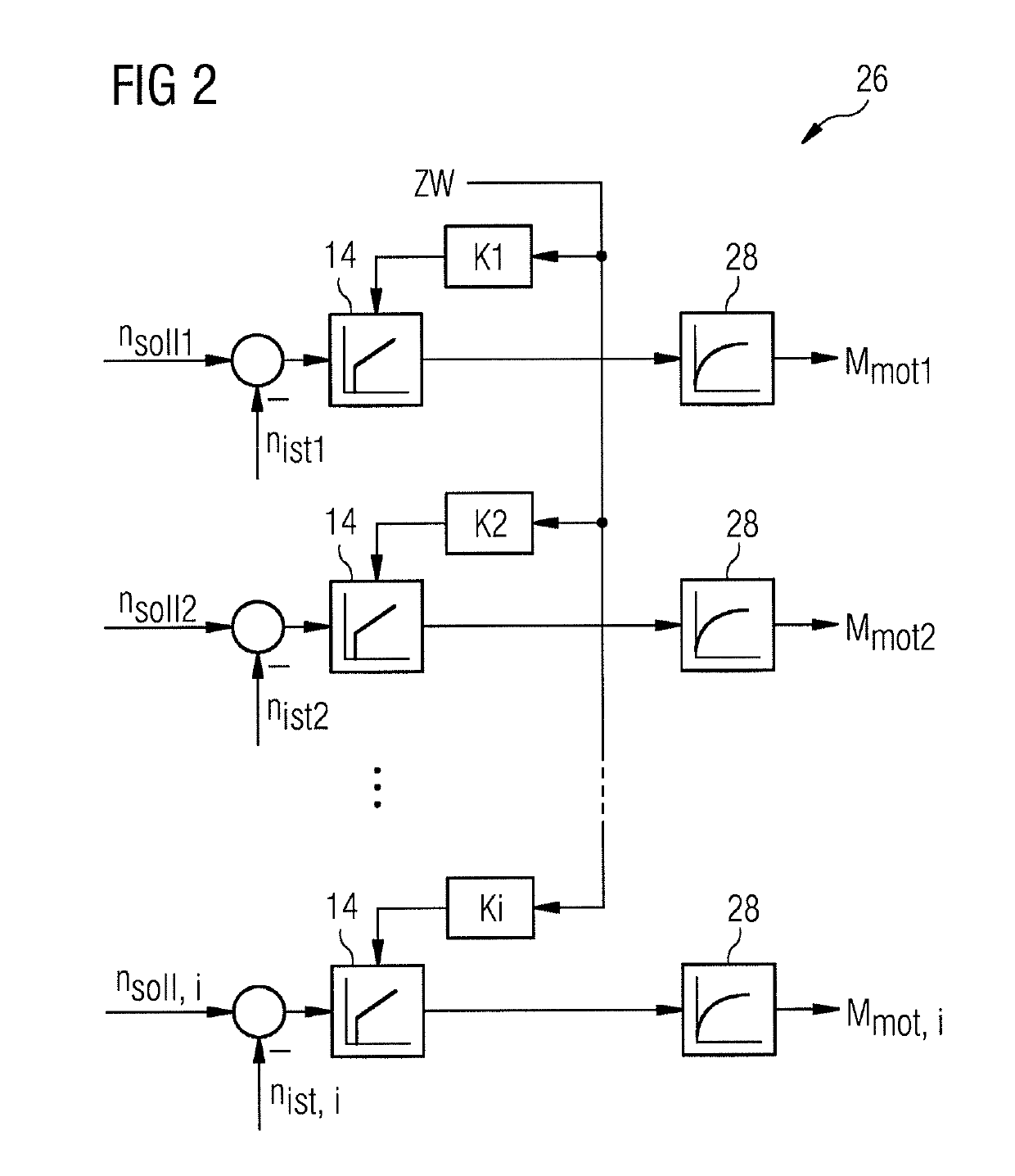
[0016]Thus, at the point in time when the first roll stand is broached, all the rotational speed regulators of all the drives in a rolling section are simultaneously preloaded with the supplementary value to ensure simultaneous anticipatory control of the roll rotational speeds for all the roll stands, and hence a balanced running of all the drives. Here, pre-loading is to be understood as meaning that the initial value of the rotational speed regulator is set to a non-zero initial value, in order to achieve a more rapid reaction from the rotational speed regulator to a drop in rotational speed. Thus all the rotational speed regulators of all the drives in the rolling section are simultaneously subjected to the relevant supplementary value, at a point in time shortly before, simultaneous with or shortly after the point in time at which the first roll stand has a real load moment imposed on it, that is at a point in time which depends on the point in time of that imposition. By this means, on the one hand the drop in rotational speed at the first roll stand, determined by the imposition on the drive of a real load moment, is largely compensated for, or at least reduced, and loop formation before the first roll stand in a rolling section is prevented.
[0017]However because, in accordance with the invention, the supplementary value is fed not only to the rotational speed regulator for the first roll stand or the first drive, as applicable, which has the real load moment imposed on it, but also to the rotational speed regulator for each drive of each roll stand in the rolling section, not only is the drop in rotational speed reduced, at the drive on which the real load moment is imposed, but also the ratios of the rotational speeds of the roll stands in a rolling section are maintained relative to one another. By feeding the relevant supplementary value into all the rotational speed regulators, a drop in rotational speed is prevented, or a brief change in the rotational speed is effected, at all the drives. The advantage of this is both that loop formation before the first roll stand is prevented and also synchronicity of the individual roll stands to one another, that is rotational speed ratios in conformity with the pass plan, is maintained, and thereby loop formation or breakage of the wire between the individual roll stands in the rolling section is prevented.
[0018]The rotational speed regulators of the drives can incorporate various regulators, e.g. P- or PI-regulators, to which the supplementary value can be fed. However, with one preferred embodiment of the invention, the supplementary value concerned is fed to a rotational speed regulator, which incorporates a PI regulator, as the preloading value for an I-component. Here, the preloading of an I-component is to be understood as meaning that the I-component of the rotational speed regulator is set to a non-zero initial value, in order to achieve a faster reaction by the rotational speed regulator to a drop in rotational speed. Unlike a supplementary value which is additive to the starting magnitude, the preloading of the I-component of the rotational speed regulator has the advantage that the supplementary value must not be “switched off” again, but is autonomously phased out by the rotational speed regulator. An autonomous correction of the rotational speed regulator is thus effected in that the supplementary value is smoothed out by reference to a comparison of the set-point and actual values of the rotational speed.
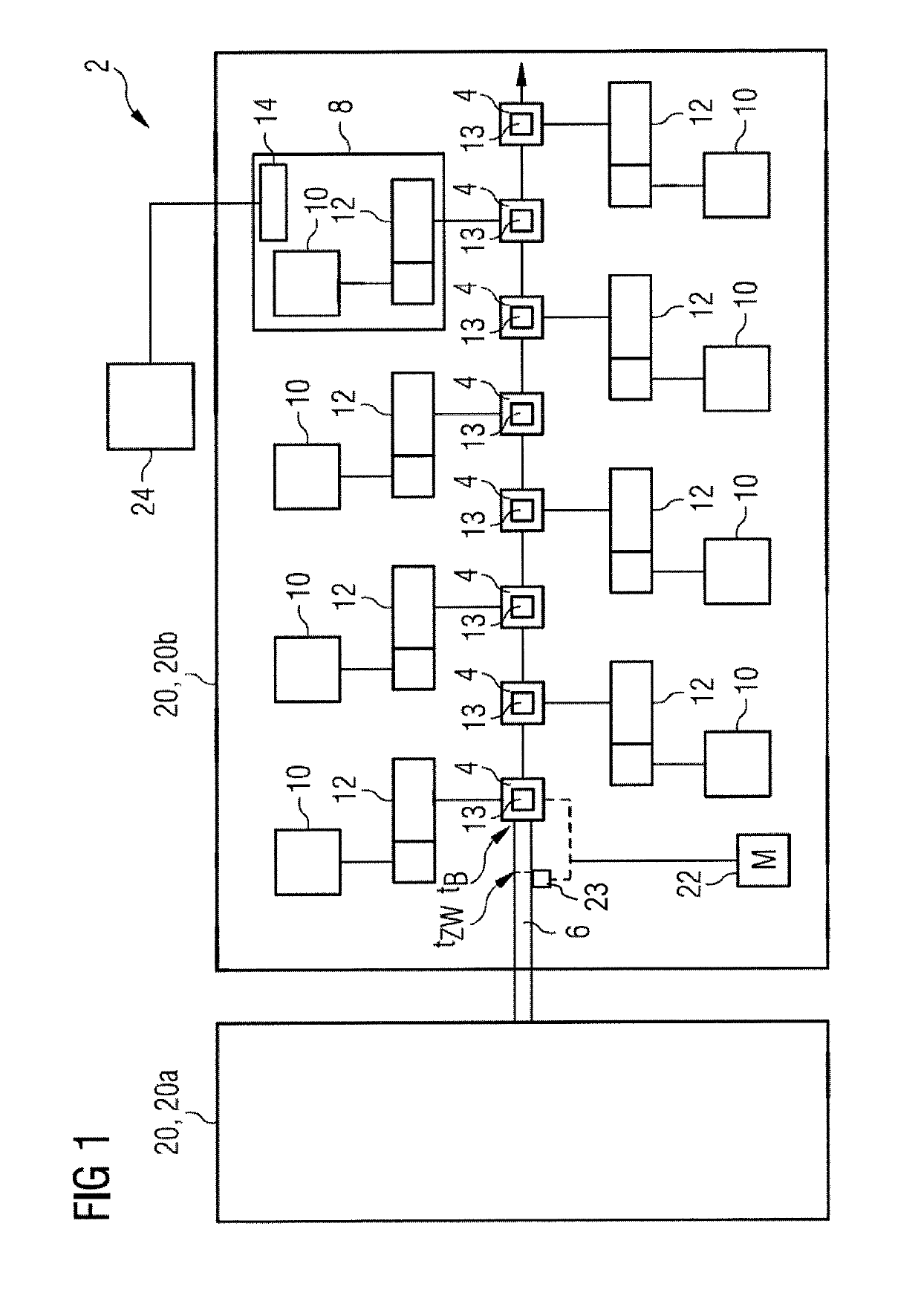
[0023]In order to be able to determine as exactly as possible the point in time at which the supplementary value should be fed, as a function of the point in time at which the first real load moment is imposed, the invention takes into account, for example, delays which occur in determining the point in time at which the load is imposed. One such delay might be, for example, the response time of the light barriers mentioned previously, which is then included in the calculation in determining the point in time at which to feed the supplementary value. This avoids, for example, a delay in the preloading of the rotational speed regulator which would be disadvantageous for the functioning of the method.

Problems solved by technology

Even small deviations can lead to a breakage of the wire or to loop formation.
However, a major disadvantage of this is that, for example, if there is wear in the individual rolling rings, it is always necessary to exchange or to regrind all the rolling rings, because the cross-sections or diameters of the bores must be matched to one another in order to achieve a desired result from the rolling.
This makes such an approach very time-consuming and costly.
However, a major challenge of such a drive solution is presented by the regulation of the rotational speed of the individual roll stands during the processing of goods which are being rolled.
This can lead to tension or compression loads, and hence a breakage of the wire, or to the material being rolled forming loops between the individual roll stands.
However, in particular if loop formation between the intermediate and finishing sections must not be permitted to occur, i.e. if the rotational speeds of the stands in the finishing section must also remain constant relative to the rotational speed of the last stand in the intermediate section, the method cited above is not adequate.

Method used


Image

  • Method for processing material to be rolled on a rolling line, and rolling line
  • Method for processing material to be rolled on a rolling line, and rolling line

Examples


Embodiment Construction

[0031]FIG. 1 shows a section of a rolling line 2 with two rolling sections 20, e.g. an intermediate section 20a and a finishing section 20b. A rolling section 20 incorporates at least two roll stands 4 each with at least one roll 13, e.g. two rolls 13, for the processing of a material to be rolled 6. FIG. 1 shows, by way of example, eight successive roll stands 4, for the sake of clarity only illustrating those for the finishing block 20b, of a rolling section 20 through which passes the material to be rolled 6, e.g. a billet which is being rolled down to wire.

[0032]Assigned to each roll stand 4 is a separate drive 8, incorporating a motor 10 and a gearbox 12, with a rotational speed regulator 14 which, for the sake of clarity, in FIG. 1 is only drawn in for one roll stand 4. The rotational speed regulator 14 regulates the rolls 13 of the drive 8 concerned to a setpoint value, nSoll, for the rotational speed. For this purpose, an actual value of the rotational speed, nIst, is contin...


PUM

PropertyMeasurementUnit
rotational speedaaaaaaaaaa
rotation speedsaaaaaaaaaa
timeaaaaaaaaaa

Abstract

A method for machining rolled stock (6) in a rolling train (2), the train including at least one rolling block (20, 20a, 20b) having at least two rolling stands (4) with each stand including at least one roll (13). Each rolling stand (4) has a separate drive (8) with a speed controller (14) for its roll (13). A time (tzw) that is dependent on the point in time (tB) that an actual loading moment is applied to the drive (8) of the first rolling stand (4) of the rolling block (20, 20a, 20b), for controlling the speed of the drive (8). An additional value (ZW), dependent on an expected actual loading moment, is fed to the speed controller (14) of each drive (8). Also, a rolling train (2) for machining rolled stock (6), is disclosed having the features above and having an open-loop / closed-loop control unit (24), in which software for the method is implemented.

Description

CROSS-REFERENCE TO RELATED APPLICATIONS[0001]The present application is a 35 U.S.C.§§ 371 national phase conversion of PCT / EP2014 / 067669, filed Aug. 19, 2014, which claims priority of European Patent Application No. 13181568.0, filed Aug. 23, 2013, the contents of which are incorporated by reference herein. The PCT International Application was published in the German language.[0002]The invention relates to a method for the processing of material, particularly steel or another metal to be rolled on a rolling line with at least two roll stands each having at least one roll. A separate drive is assigned to each roll stand for its at least one roll, and a rolling line.TECHNICAL BACKGROUND[0003]In the processing of rolled materials, e.g. steel or various metals, which are in the form of so-called slabs or billets, the material being rolled passes along a rolling line with several rolling sections. The sections for example include a roughing, an intermediate and a finishing section. In t...

Claims


Application Information

Patent Timeline
Patent Type & Authority Patents(United States)
IPC IPC(8): B21D37/00B21B37/46B21B37/52
CPCB21B37/46B21B37/52
Inventor WEISSHAAR, BERNHARD
Owner PRIMETALS TECH GERMANY
Why Eureka
Try Eureka