
Aircraft wing with a wing tip device and a strut

a technology of wing tip and strut, which is applied in the direction of airflow influencers, spars/stringers, transportation and packaging, etc., can solve the problems of difficult to efficiently distribute the load generated by the wing tip device during use, add weight and/or complexity to the retrofitting or forward-fitting process of the wing tip device, and the scope of modifying the structure of the wing is often very limited, so as to achieve fewer structural modifications and facilitate weight saving

Active Publication Date: 2019-12-10
AIRBUS OPERATIONS LTD
View PDF27 Cites 2 Cited by
  • Summary
  • Abstract
  • Description
  • Claims
  • Application Information

AI Technical Summary

Benefits of technology

The invention disclosed in this patent describes a method for installing a wing tip device on a wing using a strut. The strut helps transfer some of the loadings on the wing tip device to a more inboard location on the wing, which can better handle those loadings and allow for the use of stronger fasteners. This method also allows for a lighter and stronger wing tip device to be installed, without compromising safety. Additionally, the first connection between the wing and the wing tip device allows for bending moments to be transferred across it, which can make the installation process easier. Overall, this invention provides a more efficient and effective solution for installing wing tip devices.

Problems solved by technology

A problem when attempting to retro-fit or forward-fit a wing tip device is that the wing (to which the tip devices is being fitted) was not originally designed to receive the wing tip device.
In both these arrangements, it can be difficult to efficiently distribute the loads generated by the wing tip device during use.
This problem is especially acute for large wing tip devices (which are becoming increasingly popular).
This can add weight and / or complexity to the process of retro-fitting or forward-fitting the wing tip device.
Furthermore, the scope for modifying the structure of the wing is often very limited, so the structural reinforcements are often sub-optimal, compared to if they had been able to be incorporated into the wing during the initial design process.
However, this arrangement is not really suitable for a retro-fit or a forward fit application, because the structural modifications to the wing are too significant.

Method used


Image

  • Aircraft wing with a wing tip device and a strut
  • Aircraft wing with a wing tip device and a strut
  • Aircraft wing with a wing tip device and a strut

Examples


first embodiment

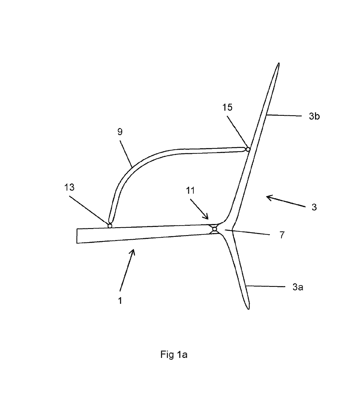
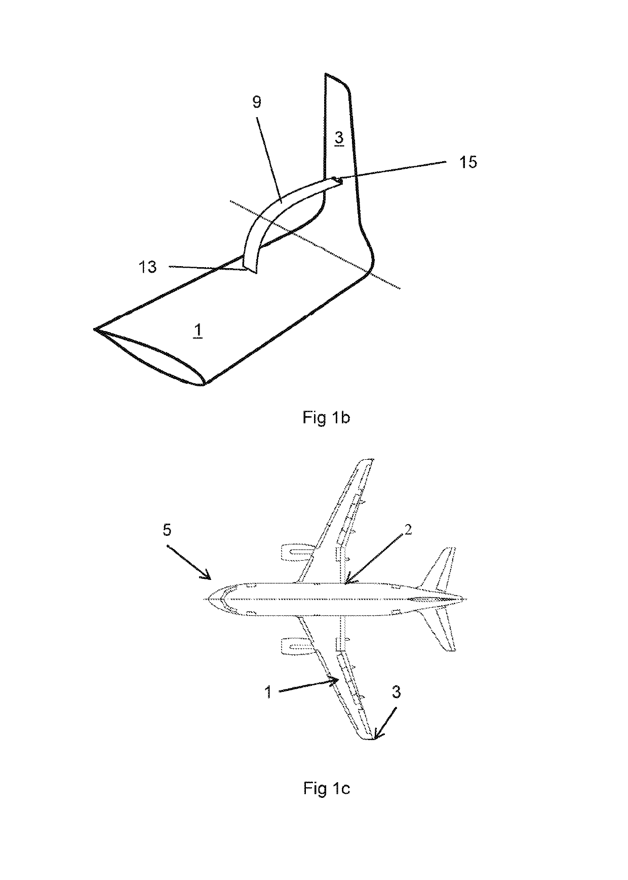
[0049]In contrast to known arrangements, the wing tip device 3 in the first embodiment is braced by an external strut 9 (see also 209, 309, 409, 509, 609, 709, 809, 909, 1009, 1109 and 1309) extending from a second connection (e.g., joint) 13 (see also 213, 313, 413, 513, 613, 713, 813, 913, 1013, 1113, 1213, 1313 and 1413) on the wing 1 to third connection (e.g., joint) 15 (see also 215, 315, 415, 515, 615, 915, 1115, 1315 and 1415) approximately mid-way along the upwardly extending part 3b of the wing tip device 3. The strut 9 transfers the majority of aerodynamic loadings on the wing tip device (generated during use) to the wing 1. The loadings are transferred to the wing 1 at the second joint 13. Thus, by virtue of the strut 9, the loadings that would normally be reacted through the joint at the wing tip / wing tip device root, are instead transferred to a location further inboard on the wing 1.

[0050]Such an arrangement has a number of benefits from a structural perspective. In pa...

fourth embodiment

[0060]FIG. 12 shown the arrangement of the invention (FIG. 4) but wherein the wing tip device is arranged to rotate to reduce the span. Such a span reduction is especially pronounced (for a given angular rotation) when using the planar wing extension 1203b.

[0061]FIGS. 13a to 13c are schematics showing some further embodiments of the invention in which a wing tip device 1303 is braced by the strut 1309 to transfer loads into the wing 1301 at a location inboard of the wing tip root 1307 (see also 1407).

[0062]FIGS. 14a and 14b are schematics showing some further embodiments of the invention in which a wing tip device 1403 is braced by the strut 1409 to transfer loads into the wing 1401 at a location inboard of the wing tip root 1407. In both these embodiments, the wing comprises a stub 1417 connected to a wing rib (not shown). The stub 1417 facilitates a straightforward connection to the strut 1409. This is a particularly attractive embodiment when the wing tip device 1403 is being fo...


PUM


Abstract

An aircraft wing (1) has a wing tip device (3) joined thereto. The root (7) of the wing tip device (3) is joined to the tip of the wing (1) at a first connection (11). An external strut (9) extends between the wing (1) and the wing tip device (3), the strut (9) being joined to the wing (1) at a second connection (13). The second connection (13) is inboard of the first connection, such that loadings on the wing tip device (3) generated during use, are transferred, via the strut (9), to a location on the wing (1) that is inboard of where the root (7) of the wing tip device (3) is joined to the tip of the wing.

Description

RELATED APPLICATIONS[0001]This application is the U.S. national phase of International Application No. PCT / GB2015 / 051033 filed Apr. 2, 2015, which designated the U.S. and claims priority to Great Britain Patent Application GB 1406091.7 filed 4 Apr. 2014, the entire contents of these applications are incorporated by reference.BACKGROUND OF THE INVENTION[0002]The present invention relates to an aircraft wing with a wing tip device and strut extending between the wing and the wing tip device, an aircraft incorporating such a wing, and to methods of modifying an aircraft wing to install a wing tip device.[0003]In recent years, it has become increasingly desirable to install wing tip devices to aircraft wings. It is known to install wing tip devices onto aircraft that are already in use (for example a wing tip device may be added during a major maintenance overhaul of the aircraft). This is commonly referred to as “retro-fitting” the wing tip device. It is also known to install wing tip ...

Claims


Application Information

Patent Timeline
Patent Type & Authority Patents(United States)
IPC IPC(8): B64C23/06B64C3/56B64C3/54B64C3/18
CPCB64C3/546B64C23/072B64C3/54B64C3/185B64C3/56Y02T50/14Y02T50/164B64C5/08B64C23/065Y02T50/10
Inventor LYNAS, CHRISTOPHERTHOMPSON, ROBERTWILLIAMS, LLIFONHOBDAY, JOHN
Owner AIRBUS OPERATIONS LTD
Learn More