Auto tensioner and auto tensioner-integrated engine auxiliary device

a technology of auxiliary devices and auto tensioners, which is applied in the field of auto tensioners and integrated engine auxiliary devices, can solve the problems of difficult to implement compact layouts of auto tensioners and belts, and achieve the effects of reducing the length of the power transmission belt, increasing the mounting space, and reducing the size of the packag

Active Publication Date: 2019-12-17
HYUNDAI MOTOR CO LTD
View PDF30 Cites 1 Cited by
  • Summary
  • Abstract
  • Description
  • Claims
  • Application Information

AI Technical Summary

Benefits of technology

[0005]The auxiliary devices, which are connected to one another by the belt and receive the driving power from the engine, are equipped with an auto tensioner as a tension adjusting device for adjusting tension of the belt in order to prevent deterioration in power transmission efficiency, and the auto tensioner is typically mounted in a movement trajectory of the belt and imparts predetermined tension to a belt surface.
[0009]In particular, the present disclosure has been made in an effort to provide an auto tensioner-integrated engine auxiliary device in which a driving member is connected to a driven pulley of an engine auxiliary device (e.g., a water pump pulley) which is rotated by an operation of a belt such that belt tension may be adjusted by an eccentric movement of the driven pulley, and rotational power of the driven pulley may be normally and effectively transmitted to an output unit of the engine auxiliary device (e.g., a water pump impeller).
[0028]According to the present disclosure, since the water pump pulley performs a function of a tensioner pulley which was used to adjust tension of the existing power transmission belt, it is possible to omit the existing tensioner pulley, reduce a size of a package, increase a mounting space, reduce a length of the power transmission belt, reduce costs and a weight, and improve fuel economy. In addition, it is possible to implement a compact and simple layout of the power transmission belt to which the engine auxiliary device and the auto tensioner are applied.

Problems solved by technology

However, in the related art, because of a structure of a cooling system including a water pump for circulating a coolant for cooling the engine, the water pump is positioned at the middle of various engine auxiliary devices connected to one another by the belt, and as a result, there is a problem in that it is difficult to implement compact layouts of the auto tensioner and the belt.

Method used


Image

  • Auto tensioner and auto tensioner-integrated engine auxiliary device
  • Auto tensioner and auto tensioner-integrated engine auxiliary device
  • Auto tensioner and auto tensioner-integrated engine auxiliary device

Examples


Embodiment Construction

[0043]Hereinafter reference will now be made in detail to various embodiments of the present disclosure, examples of which are illustrated in the accompanying drawings and described below. While the invention will be described in conjunction with exemplary embodiments, it will be understood that present description is not intended to limit the invention to those exemplary embodiments. On the contrary, the invention is intended to cover not only the exemplary embodiments, but also various alternatives, modifications, equivalents and other embodiments, which may be included within the spirit and scope of the invention as defined by the appended claims.

[0044]Hereinafter, an exemplary embodiment of the present disclosure will be described in detail with reference to the accompanying drawings.

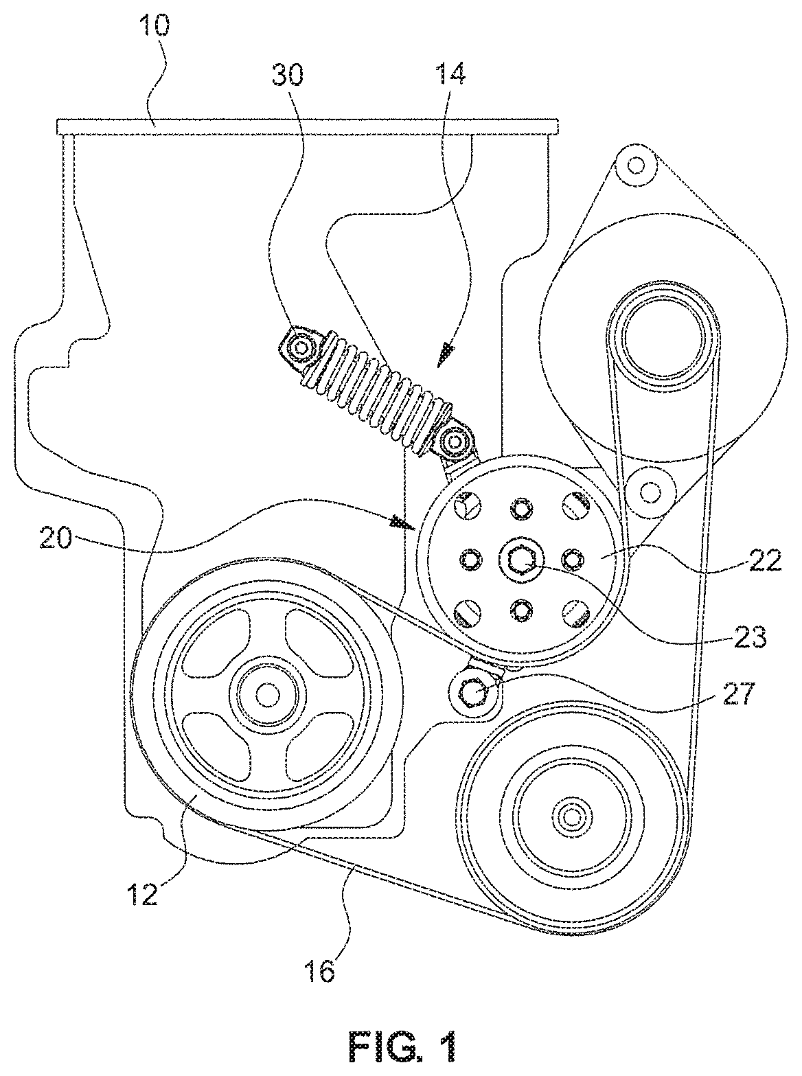
[0045]As illustrated in FIG. 1, driven pulleys of various types of engine auxiliary devices (a generator, a water pump, or an air-conditioner compressor) are connected to a crank shaft pulley 12 of ...


PUM


Abstract

An auto tensioner is mounted on a rotating shaft of an engine auxiliary device rotating about the rotating shaft by a power transmitted through a power transmission belt. The auto tensioner pivots about a pivot shaft. The auto tensioner has one side rotatably fastened to the pivot shaft and another side fastened to a driving member, and pivots about the pivot shaft in accordance with an operation of the driving member.

Description

CROSS-REFERENCE TO RELATED APPLICATION[0001]This application claims under 35 U.S.C. § 119(a) the benefit of priority to Korean Patent Application No. 10-2016-0094482 filed on Jul. 26, 2016, the entire content of which is incorporated herein by reference.TECHNICAL FIELD[0002]The present disclosure relates to an auto tensioner and an auto tensioner-integrated engine auxiliary device. More particularly, the present disclosure relates to an auto tensioner and an auto tensioner-integrated engine auxiliary device, which are capable of normally performing both a function of the engine auxiliary device and a function of adjusting tension of a power transmission belt.SUMMARY[0003]In general, driving power generated by an engine of an automobile is used as a power source for driving engine auxiliary devices as well as for rotating vehicle wheels to allow the automobile to travel, and as the auxiliary devices that use driving power from the engine as a power source as described above, there ar...

Claims


Application Information

Patent Timeline
Patent Type & Authority Patents(United States)
IPC IPC(8): F16H7/16F02B67/06F01P5/12F16H7/14F16H55/36F16H7/08F16H39/00
CPCF16H55/36F01P5/12F16H7/16F02B67/06F16H7/14F16H39/00F16H2007/0808F16H2007/0806F16H2007/0893F16H2007/0865F16H2007/0812F16H7/08F16H2007/0842F16H2007/0863F01P5/10F16H7/12
Inventor LEE, BYUNG HYUN
Owner HYUNDAI MOTOR CO LTD
Why Eureka
Try Eureka