Heater and glow plug equipped with same

a technology of heater and glow plug, which is applied in the direction of heater elements, ohmic-resistance heating, lighting and heating apparatus, etc., can solve the problems of difficult transmission, possible degradation of long-term reliability of heater, and cracks in the circumferential direction

Active Publication Date: 2020-01-14
KYOCERA CORP
View PDF10 Cites 1 Cited by
  • Summary
  • Abstract
  • Description
  • Claims
  • Application Information

AI Technical Summary

Problems solved by technology

Nevertheless, when a high current is supplied to the heat-generating element, a possibility arises that heat generation occurs locally in a part of the heat-generating element so that a large thermal expansion occurs in that part of the heat-generating element.
Then, a possibility is caused that the large thermal expansion having occurred in the heat-generating element generates cracks between the heat-generating element and the ceramic-made substrate.
In particular, like in the ceramic heater disclosed in Patent Literature 1, when the cross section of the heat-generating element has a circular shape, generated cracks easily propagate along the interface between the heat-generating element and the substrate and hence a possibility is caused that the cracks grow in the circumferential direction.
As a result, gaps are generates between the heat-generating element and the substrate so that the heat generated in the heat-generating element becomes difficult to be transmitted to the substrate and hence a possibility of degradation of the long term reliability of the heater is caused.

Method used


Image

  • Heater and glow plug equipped with same
  • Heater and glow plug equipped with same
  • Heater and glow plug equipped with same

Examples


Embodiment Construction

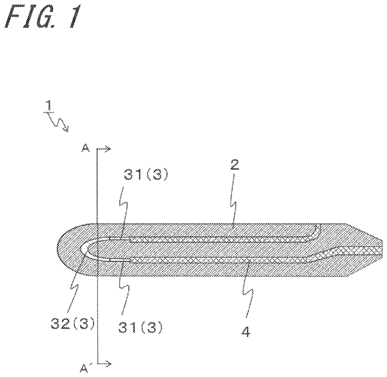
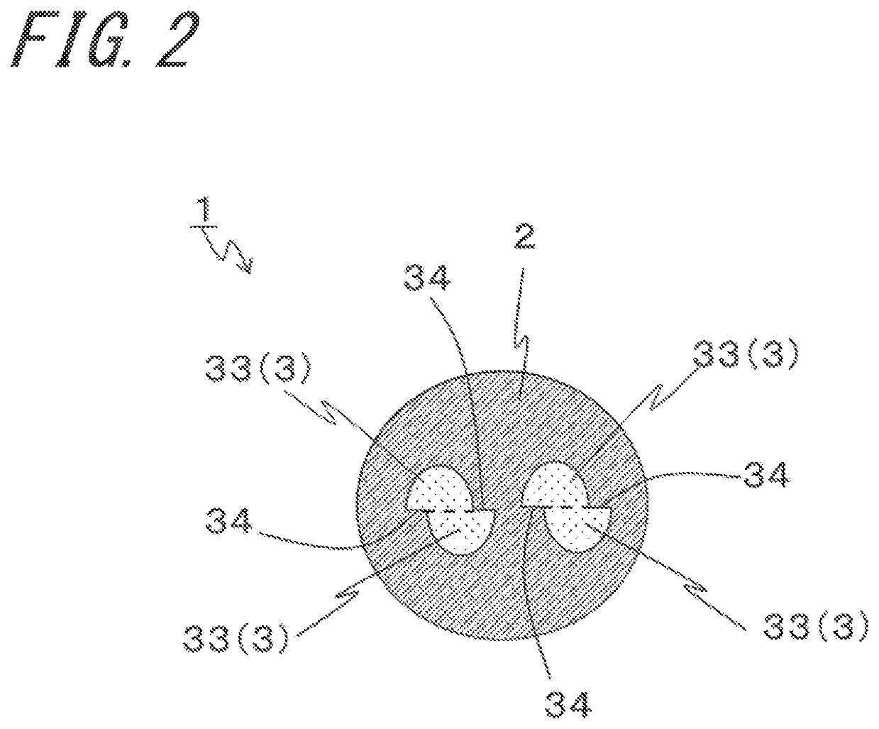
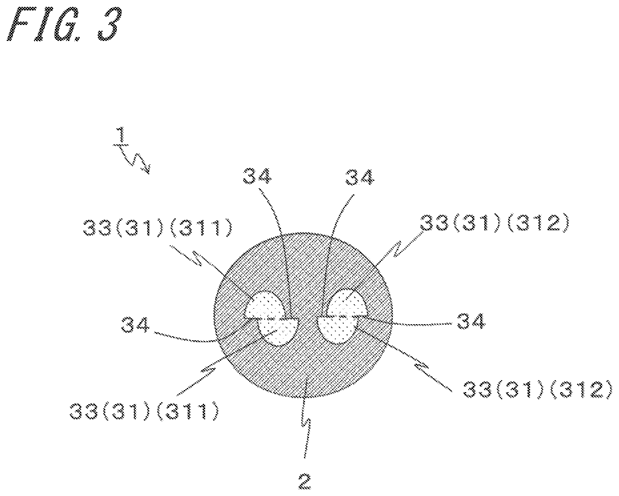
[0015]As shown in FIG. 1, a heater 1 includes: a ceramic body 2; a heat-generating resistor 3 buried in the ceramic body 2; and leads 4 connected to the heat-generating resistor 3 and then drawn out to a surface of the ceramic body 2.

[0016]For example, the ceramic body 2 in the heater 1 is formed in a bar shape having a longitudinal direction thereof. The heat-generating resistor 3 and the leads 4 are buried in the ceramic body 2. Here, the ceramic body 2 is formed of ceramics. This realizes the heater 1 having higher reliability at the time of rapid temperature raising. Employable ceramics include ceramics having electrical insulation such as oxide ceramics, nitride ceramics, and carbide ceramics. In particular, the ceramic body 2 is preferably formed of silicon-nitride based ceramics. This is because, in the silicon-nitride based ceramics, silicon nitride contained as the main component is excellent from the perspectives of strength, toughness, insulation, and heat resistance. For...


PUM


Abstract

A heater includes a ceramic body of bar shape; and a heat-generating resistor disposed in an inside of the ceramic body, when viewed in a transverse section, the heat-generating resistor including at least one step portion provided in an outer periphery part of the heat-generating resistor, the at least one step portion having such a shape that semicircular portions bisected in a diametrical direction of the heat-generating resistor deviate from each other along the diametrical direction.

Description

TECHNICAL FIELD[0001]The present disclosure relates to a heater utilized as a heater for ignition or for flame detection used in a combustion-type vehicle-mounted heating apparatus or the like, a heater for ignition used in a burning appliance of diverse kind such as a kerosene fan heater, a heater for glow plug used in a diesel engine, a heater for sensor of diverse kind such as an oxygen sensor, a heater for heating used in measuring equipment, or any other heater; and a glow plug provided with the same.BACKGROUND ART[0002]As a heater, for example, a ceramic heater disclosed in Japanese Unexamined Patent Publication JP-A 2007-240080 (referred to as Patent Literature 1, hereinafter) is known. The ceramic heater disclosed in Patent Document 1 includes: a substrate having a bar shape and formed of ceramics; and a heat-generating element buried in the substrate. The heat-generating element includes a pair of bar-shaped electrically conductive parts extending in an axial direction ther...

Claims


Application Information

Patent Timeline
Patent Type & Authority Patents(United States)
IPC IPC(8): F23Q7/00F23Q7/06H05B3/14H05B3/48H05B3/06
CPCF23Q7/06F23Q7/001H05B3/48H05B3/148H05B3/06F23Q2007/002H05B2203/027
Inventor TAIMURA, KOTARO
Owner KYOCERA CORP
Why Eureka
Try Eureka