Fuel injection valve for internal combustion engines

A technology of fuel injection valve and internal combustion engine, which is applied to fuel injection devices, internal combustion piston engines, combustion engines, etc., can solve problems such as unsolved fuel distribution problems, and achieve the effects of optimally controlling the amount of fuel and optimizing fuel atomization.

Inactive Publication Date: 2013-08-21
ROBERT BOSCH GMBH
View PDF11 Cites 2 Cited by
  • Summary
  • Abstract
  • Description
  • Claims
  • Application Information

AI Technical Summary

Problems solved by technology

[0011] However, all of these solutions do not solve the problem of differential fuel distribution due to detached valve needles

Method used


Image

  • Fuel injection valve for internal combustion engines
  • Fuel injection valve for internal combustion engines
  • Fuel injection valve for internal combustion engines

Examples


Embodiment Construction

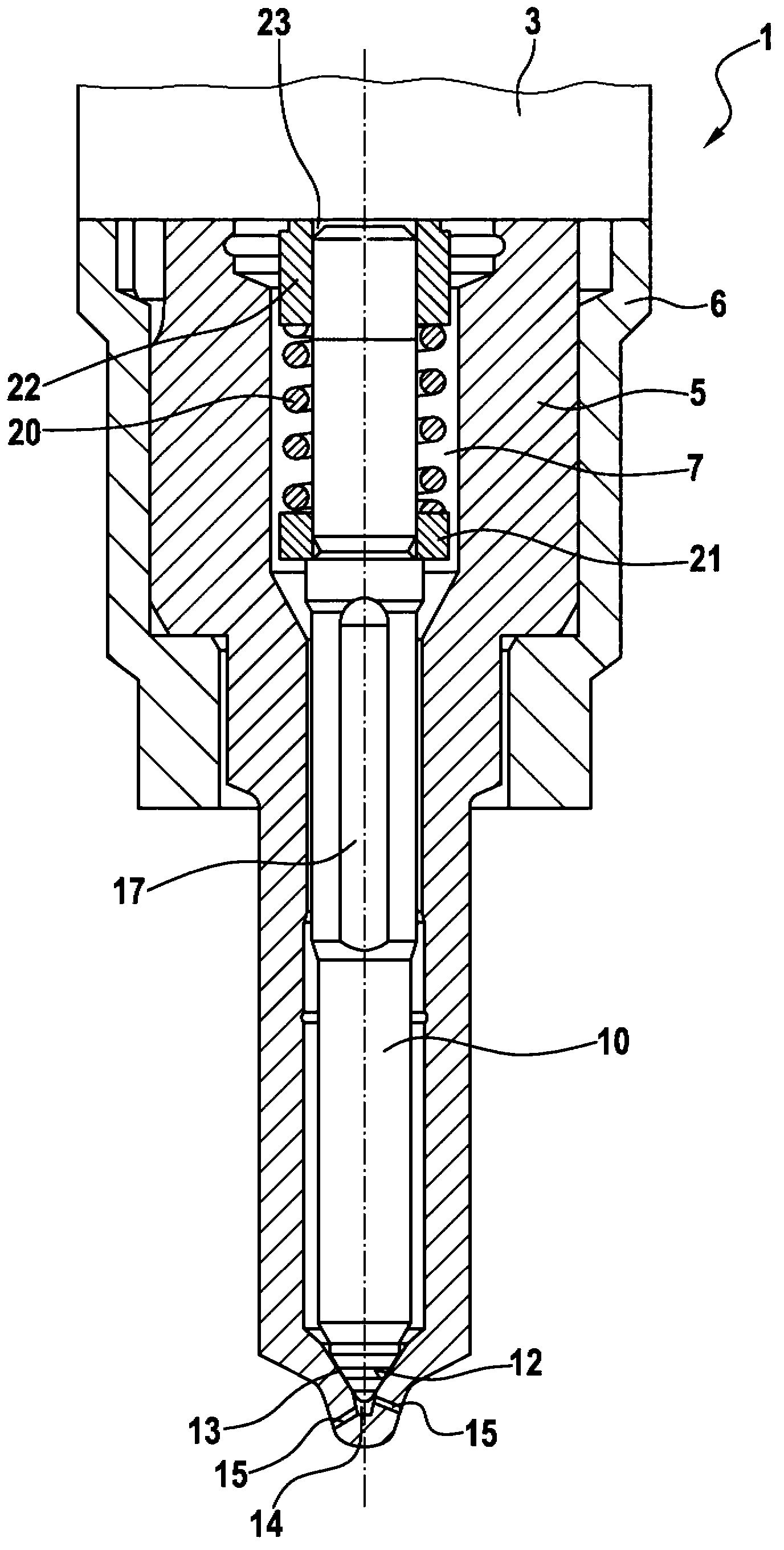
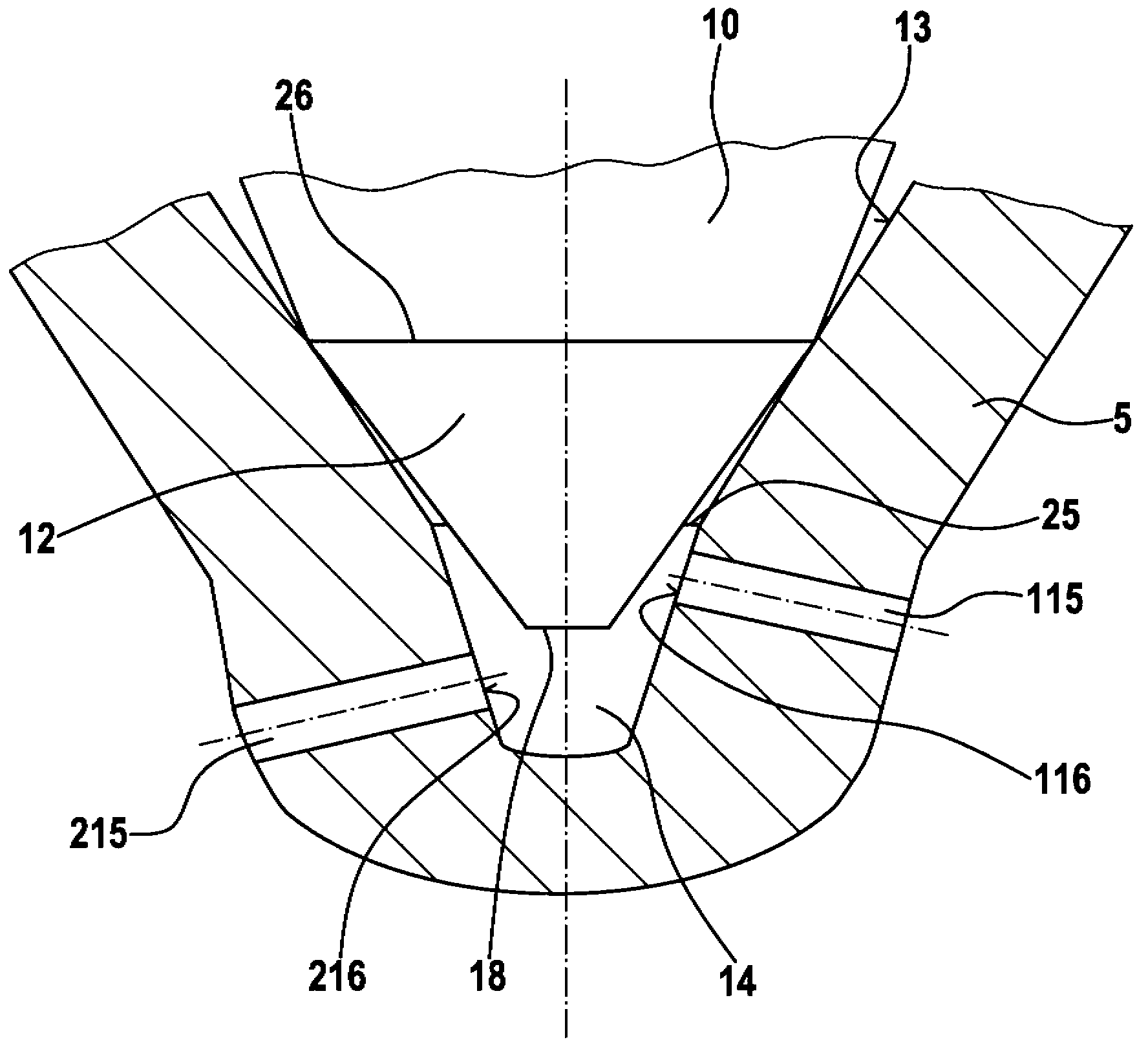
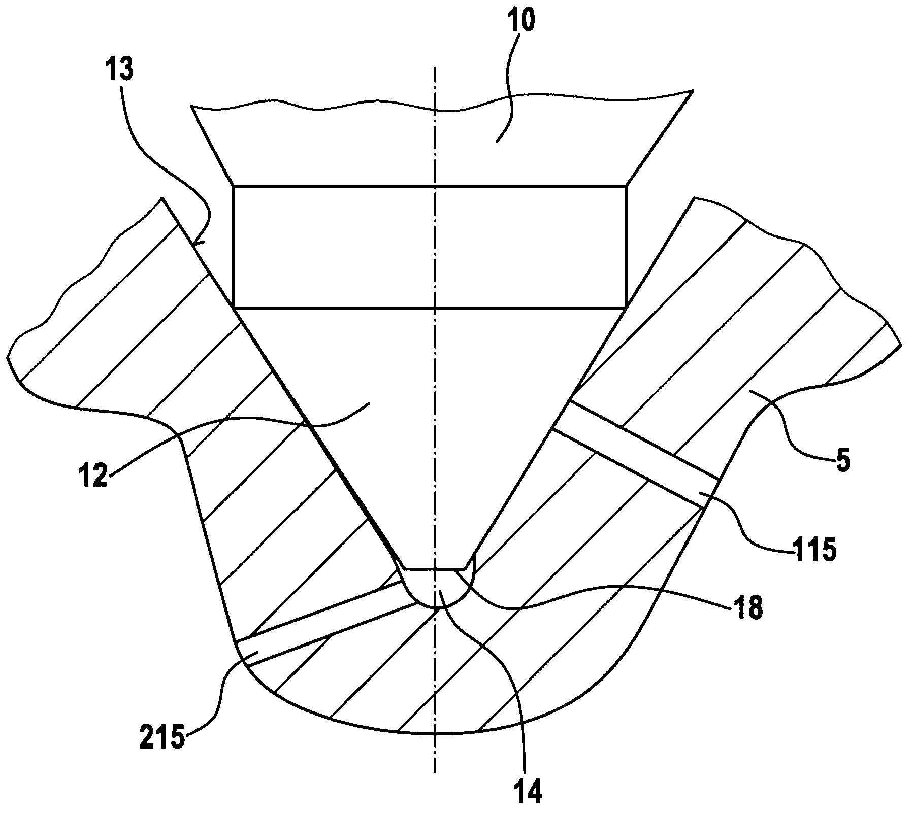
[0026] exist figure 1 shows a fuel injector 1 according to the invention. The fuel injector comprises a holding body 3 and a valve body 5 , wherein the holding body 3 is only partially and schematically shown, while the valve body 5 is shown in longitudinal section. The valve body 5 clamps the holding body 3 by means of a clamping nut 6 and has a pressure chamber 7 which is designed as a stepped bore and is delimited at the end of the valve body 5 on the combustion chamber side by a conical valve seat 13 . At the outermost end, the valve seat 13 merges into a blind hole 14 from which a plurality of injection holes 15 originate. A piston-shaped valve needle 10 is arranged longitudinally displaceable in the pressure chamber 7 and is guided in the central region of the pressure chamber 7 . The fuel flow is ensured in the region of the valve needle guide by a plurality of sharpenings 17 on the valve needle 10 , wherein the sharpenings 17 are formed in the region of the guide of ...


PUM


Abstract

The invention relates to a fuel injection valve (1) comprising a valve body (5), in which a pressure chamber (7) is designed which, at one end, is delimited by a conical valve seat (13) to which a blind hole (14) connects. A valve needle (10) is arranged longitudinally displaceably in the pressure chamber (7), a valve sealing face (12) of the needle cooperating with the conical valve seat (13) to control a fuel flow from the pressure chamber (7) to injection openings (15; 115; 215) designed in the valve body (5), wherein a valve needle tip (18) of the valve needle (10) protrudes in the blind hole (14) when the needle is seated against the valve seat (13).; The inlet opening (216) of an injection opening (215) is arranged downstream of the valve needle tip (18) in the blind hole (14) and the inlet openings (116) of the remaining injection holes (115) are arranged downstream of the valve needle tip (18) when the valve needle (10) is seated against the valve seat (13). An internal combustion engine comprising such a fuel injection valve (1) and a pencil-type glow plug (35) is designed such the fuel exiting the downstream injection opening (215) forms a pilot injection which is directed to or in the direct vicinity of the pencil-type glow plug (35). Because of the position of this injection opening, fuel is ejected in the direction of the pencil-type glow plug even when the valve needle is offset and even with small needle strokes.

Description

technical field [0001] The invention relates to a fuel injection valve for an internal combustion engine, which is suitable, for example, for injecting fuel directly into a combustion chamber of the internal combustion engine, in particular for self-igniting, fast-running internal combustion engines. Background technique [0002] The invention starts here from a fuel injection valve for an internal combustion engine known, for example, from DE 10 2004 050 046 A1. Such fuel injection valves have a valve body in which a longitudinally displaceable piston-shaped valve needle is arranged. The valve needle interacts with a conical valve seat, the fuel supply being controlled by the valve needle through a plurality of injection openings, whereby the fuel flow is freely formed or interrupted. The fuel injection openings here start from blind bores which adjoin the conical valve seat, wherein a plurality of injection openings are generally arranged distributed over the circumferenc...

Claims


Application Information

Patent Timeline
IPC IPC(8): F02M61/18
CPCF02B23/0648F02B23/0654F02B23/0669F02B23/0696F02M61/1813F02M61/182F02M61/1826F02M61/1886F02P19/02Y02T10/12
Inventor B·施图克M·努丁
Owner ROBERT BOSCH GMBH
Why Eureka
Try Eureka