Method and system for glow plug operation

a temperature management and operation technology, applied in the field of glow plugs, can solve the problems of low reliability of glow plugs, drawbacks of glow plugs,

Active Publication Date: 2022-05-19
PRATT & WHITNEY CANADA CORP
View PDF12 Cites 1 Cited by
  • Summary
  • Abstract
  • Description
  • Claims
  • Application Information

AI Technical Summary

Problems solved by technology

However, glow plugs have drawbacks.
For instance, the glow plugs have been known to achieve less than full r...

Method used


Image

  • Method and system for glow plug operation
  • Method and system for glow plug operation
  • Method and system for glow plug operation

Examples


Embodiment Construction

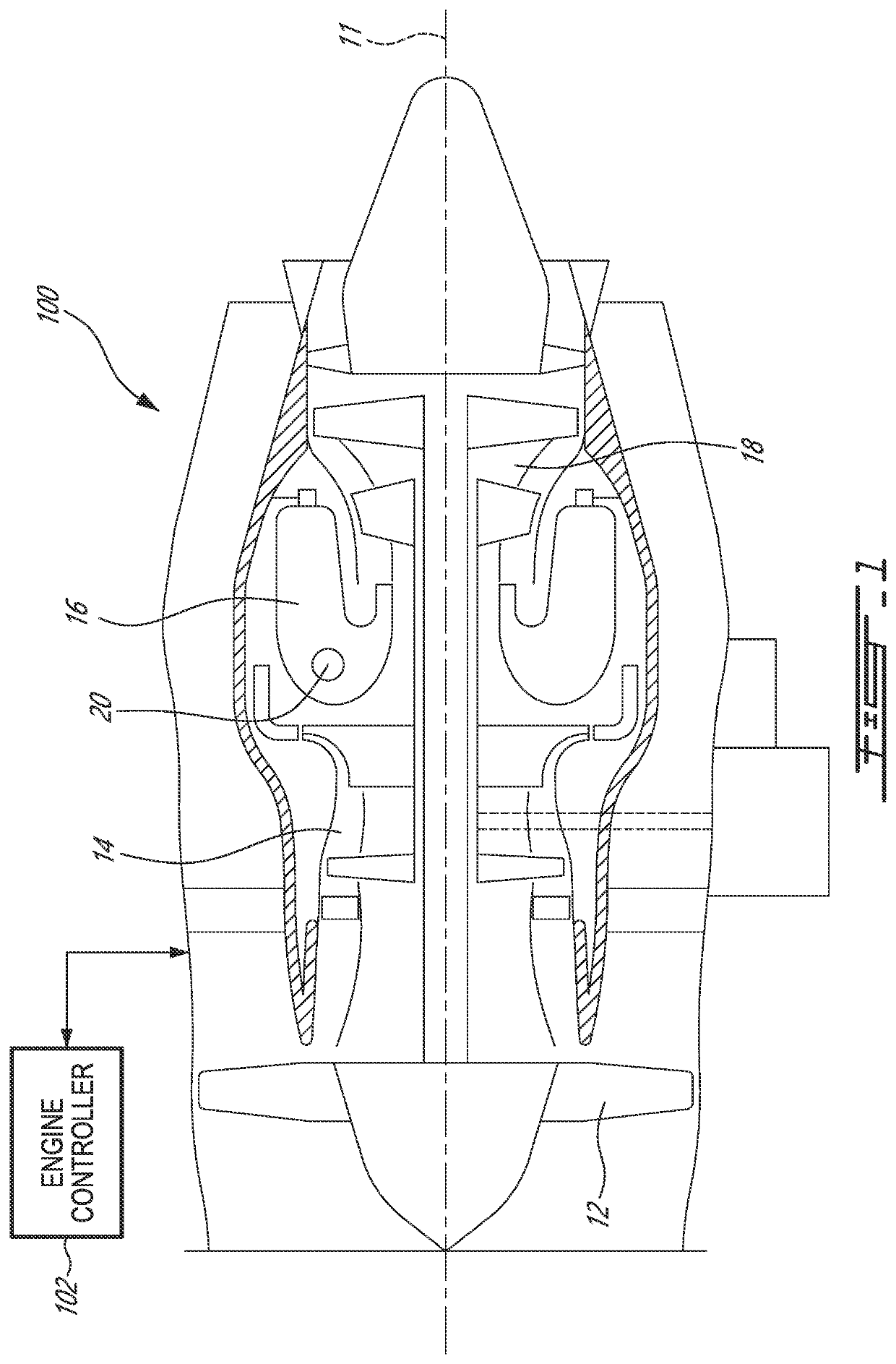
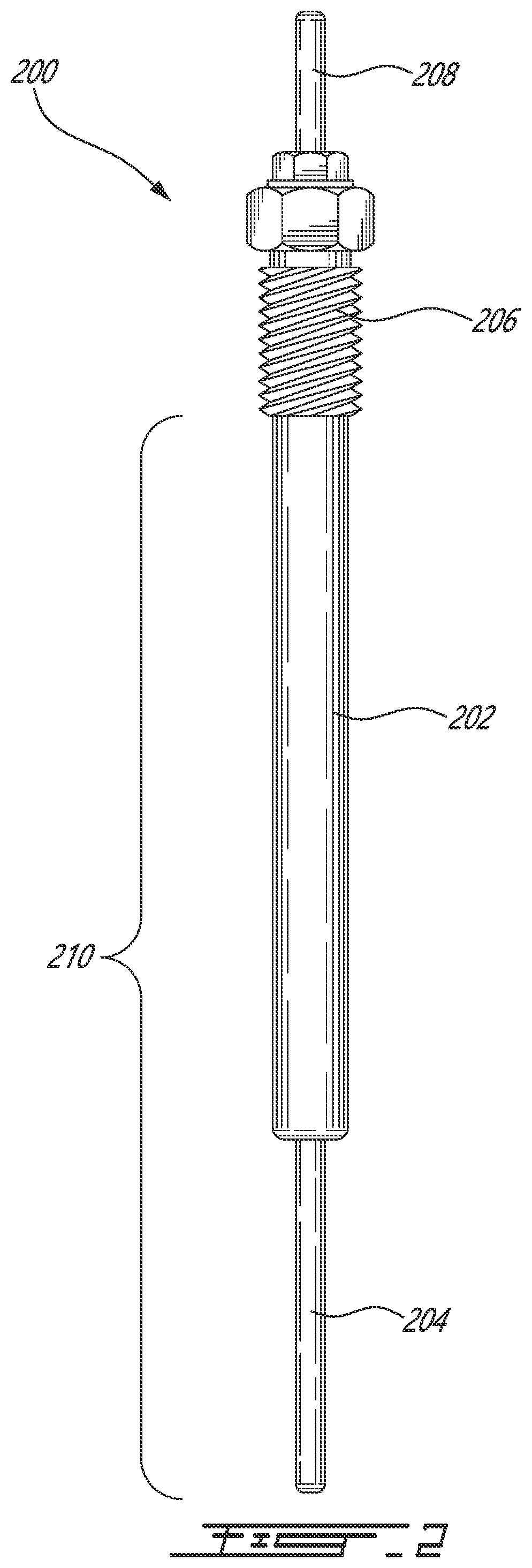
[0013]There is described herein a glow plug system and a method for operating a glow plug. In some embodiments, the glow plug is used to ignite an engine, such as a gas turbine engine. Alternatively, the glow plug may be used for any type of application requiring such a heating element. FIG. 1 illustrates a gas turbine engine 10 of a type provided for use in subsonic flight, generally comprising in serial flow communication a fan 12 through which ambient air is propelled, a compressor section 14 for pressurizing the air, a combustor 16 in which the compressed air is mixed with fuel and ignited for generating an annular stream of hot combustion gases, and a turbine section 18 for extracting energy from the combustion gases. The fan 12, the compressor section 14, and the turbine section 18 rotate about a central axis 11. The combustor 16 defines at least one aperture 20 for receiving at least one glow plug 200 (FIG. 2) for igniting the mixture of compressed air and fuel.

[0014]Control ...


PUM


Abstract

There are described methods and systems for operating a glow plug. The method comprises monitoring a glow plug current; applying a nominal voltage VN to the glow plug when the glow plug current is between an upper threshold I1 and a lower threshold I2<I1; applying a voltage VH>VN to the glow plug when the glow plug current exceeds the upper threshold I1; and applying substantially no voltage to the glow plug when the glow plug current falls below the lower threshold I2.

Description

TECHNICAL FIELD[0001]The application relates generally to glow plugs and, more particularly, to temperature management of a glow plug in operation.BACKGROUND OF THE ART[0002]Glow plugs are commonly used to ignite a mixture of air and fuel in a combustor of gas turbine engines. However, glow plugs have drawbacks. For instance, the glow plugs have been known to achieve less than full reliability in conditions such as when the fuel and the engine are very cold or when the environment gets too hot. Cost is also a factor. There is always room for improvement.SUMMARY[0003]In one aspect, there is provided a method for operating a glow plug. The method comprises monitoring a glow plug current; applying a nominal voltage VN to the glow plug when the glow plug current is between an upper threshold I1 and a lower threshold I2<I1; applying a voltage VH>VN to the glow plug when the glow plug current exceeds the upper threshold I1; and applying substantially no voltage to the glow plug when...

Claims


Application Information

Patent Timeline
IPC IPC(8): F02C7/266F02C9/00
CPCF02C7/266F02C9/00F05D2270/303F05D2260/99F05D2240/35F02P19/021F02P19/025F23Q7/00
Inventor TANJU, MEHMET CELALFREER, RICHARD
Owner PRATT & WHITNEY CANADA CORP
Why Eureka
Try Eureka