Downhole flow diversion device with oscillation damper

a technology of flow diversion device and damper, which is applied in the direction of borehole/well accessories, well/borehole valve arrangement, construction, etc., can solve the problems of limiting the amount of fluid flow, being unable to drill holes, and requiring a large amount of pressure, so as to achieve the effect of dampening the axial motion of the piston

Active Publication Date: 2020-01-28
DYNOMAX DRILLING TOOLS USA INC
View PDF44 Cites 3 Cited by
  • Summary
  • Abstract
  • Description
  • Claims
  • Application Information

AI Technical Summary

Benefits of technology

[0005]Embodiments of a system, method and apparatus for controlling fluid flow through a drill string are disclosed. For example, an apparatus may include a housing having an axis, a radial wall with a bore extending axially therethrough, and an aperture formed in the radial wall. The aperture is in fluid communication with the bore. A piston may be located inside the housing and have an orifice configured to permit axial fluid flow through the housing. A spring may be located in the housing and be configured to axially bias the piston to a closed position. A viscous damper can dampen axial motion of the piston.
[0006]In other embodiments, a method of controlling fluid flow through a drill string may include operating the drill string to drill a hole in an earthen formation; pumping fluid through the drill string to a mud motor such that substantially all of the fluid is flows axially to the mud motor and substantially none of the fluid is radially diverted out of the drill string; and then increasing a flow rate of the fluid such that some of the fluid is radially diverted out of the drill string by a valve before reaching the mud motor, and a remainder of the fluid is flows axially to the mud motor. A viscous damper can dampen motion of the valve in both axial directions.

Problems solved by technology

Without this cleaning action the cut pieces of rock would accumulate near the drill bit and it would become impossible to drill the hole.
However, there are several factors that limit the amount of fluid flow, such as the amount of pressure that it takes to pump a large amount of fluid.
As the drill string becomes longer or narrower pumping a given amount of fluid encounters more and more resistance and therefore a high amount of pressure is required.
With any fluid pump set up there is always a limit to the amount of pressure that can be overcome in order to make the fluid flow, so the size or type of pump that is available on drilling rate can limit the available flow rate.
Another limiting factor is the capability of the downhole mud motor.
Forcing more fluid through the motor then it is designed for will result in damage to the motor and will inhibit the drilling process.
The desire to flow a high volume of drilling fluid through the well and the need to limit the volume flow rate due to the constraints of the motor are often conflicting.

Method used


Image

  • Downhole flow diversion device with oscillation damper
  • Downhole flow diversion device with oscillation damper
  • Downhole flow diversion device with oscillation damper

Examples


Embodiment Construction

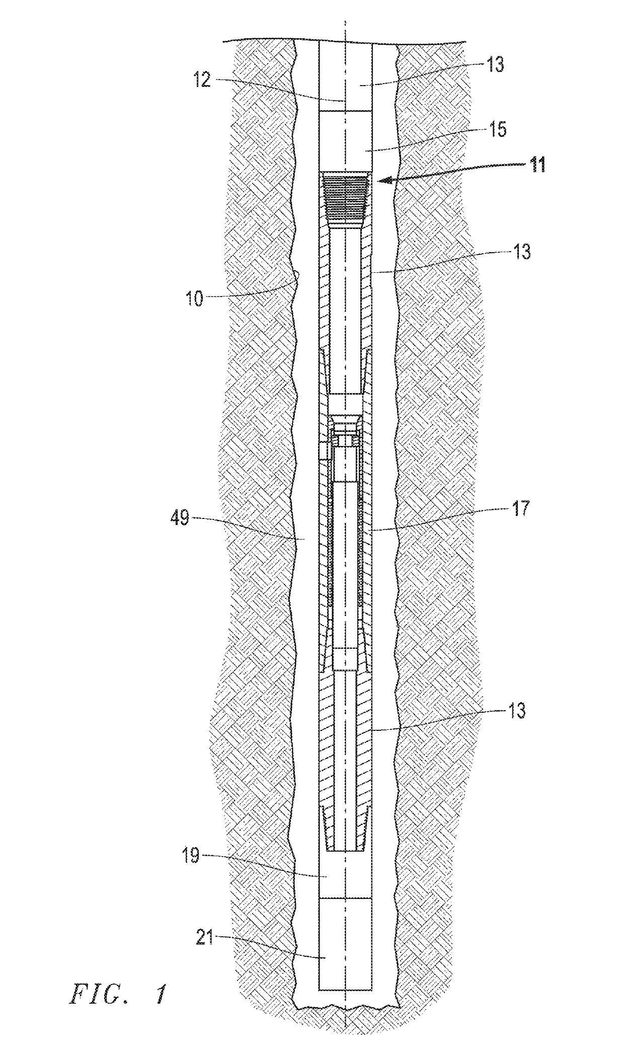
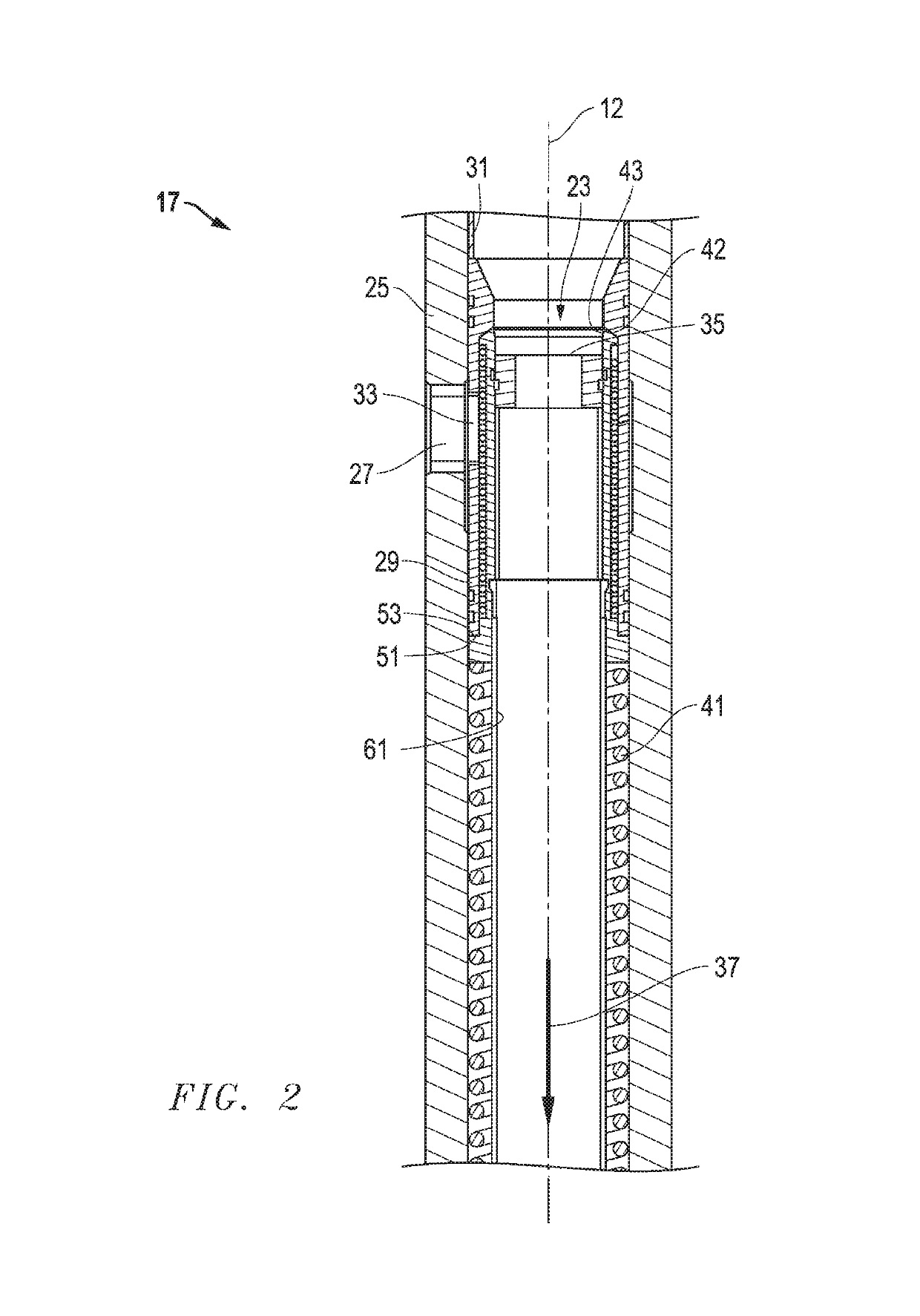
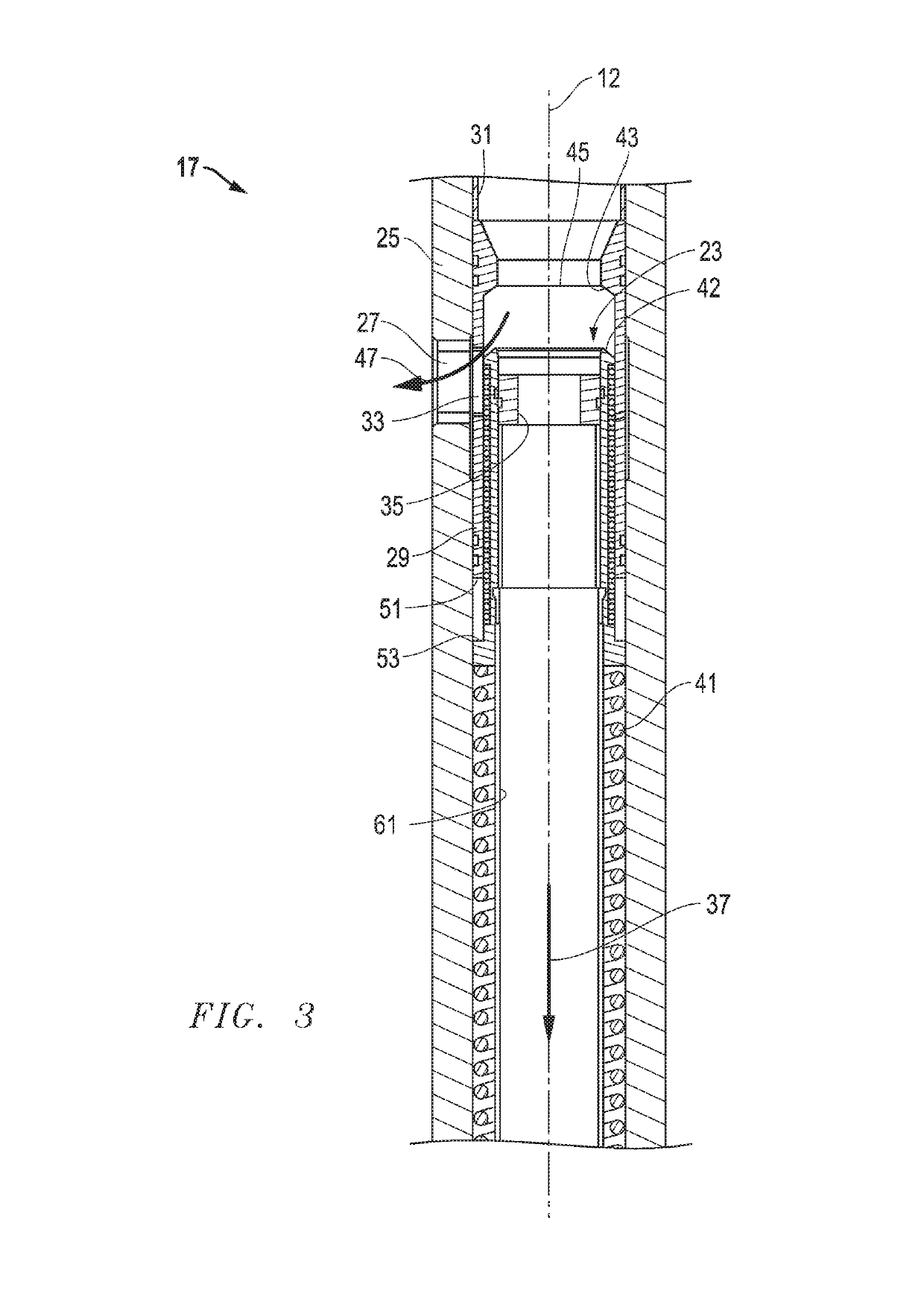
[0019]Drill string fluid flow may be better controlled with radial ports in the drill string above the mud motor. By choosing the size of the ports carefully, the amount of flow that exits through the ports and the amount of flow that continues on through the drill string into the mud motor can be controlled. The amount of fluid that exits through the ports will vary depending on the back pressure from the mud motor. The back pressure from the mud motor is a factor of how much torque it delivers, so the more torque that is needed or generated by the motor, the higher the back pressure from the motor, and more fluid is radially diverted out of the drill string. The more fluid that is radially diverted out of the drill string, the less fluid that is delivered to the motor. When less fluid goes through the motor the amount of torque that the motor can generate falls, and so a situation can develop where the motor stalls and needs more torque to overcome its boundary condition, which re...


PUM


Abstract

A device for limiting the flow of drilling fluid through a section of drill string is described. The device includes a cylindrical tube with holes in its periphery. Flow enters the device through an upper end of the tube and a portion of the flow exits through the lower end of the tube. In addition, some of the flow is diverted through the peripheral holes. A valve piston is supported near the lower end of the tube by a spring of approximately constant force through its range of travel. The valve piston moves axially as the flow rate through the tube changes flow rate to ensure that a substantially constant amount of flow exits through the lower end, while the excess flow is diverted from the tube through the peripheral holes. A means of damping or stopping the axial movement of the valve piston is included in the device.

Description

BACKGROUND OF THE INVENTIONField of the Disclosure[0001]The present invention relates in general to drill strings and, in particular, to a system, method and apparatus for regulating fluid flow through a drill string.Description of the Related Art[0002]A conventional means of drilling for oil or gas includes pumping drilling fluid through a pipe or drill string to a drill bit that is cutting the hole in the rock. The fluid is circulated back up though wellbore in the annular or outer section of the hole. Drilling fluid is beneficial to the drilling process since it clears away pieces of rock that have been cut from the bottom of the wellbore. Without this cleaning action the cut pieces of rock would accumulate near the drill bit and it would become impossible to drill the hole. In general, the higher the level of fluid flow that a drilling operation can achieve, the better that cut pieces of rock or “cuttings” are cleared from the bottom of the wellbore.[0003]However, there are seve...

Claims


Application Information

Patent Timeline
Patent Type & Authority Patents(United States)
IPC IPC(8): E21B21/10E21B4/02E21B34/08E21B34/00
CPCE21B21/103E21B34/08E21B4/02E21B2034/007E21B21/08E21B34/14E21B2200/06
Inventor CRAMER, DAVID S.HARVEY, MICHAEL J.DEVLIN, DAVID D.
Owner DYNOMAX DRILLING TOOLS USA INC
Why Eureka
Try Eureka