Secure fluid connection

Active Publication Date: 2020-02-11
SARTORIUS STEDIM FMT SAS
View PDF14 Cites 9 Cited by
  • Summary
  • Abstract
  • Description
  • Claims
  • Application Information

AI Technical Summary

Benefits of technology

[0010]With these arrangements, the fluid connection device can first be used reversibly by engaging the primary locking device, and then said connection can be made impossible to disassemble by placing the secondary locking device in its active position, in an irreversible manner; when the secondary lock reaches its active position, this position connection can no longer be exite

Problems solved by technology

However, in this document EP0462971, no means are provided

Method used


Image

  • Secure fluid connection
  • Secure fluid connection
  • Secure fluid connection

Examples


first embodiment

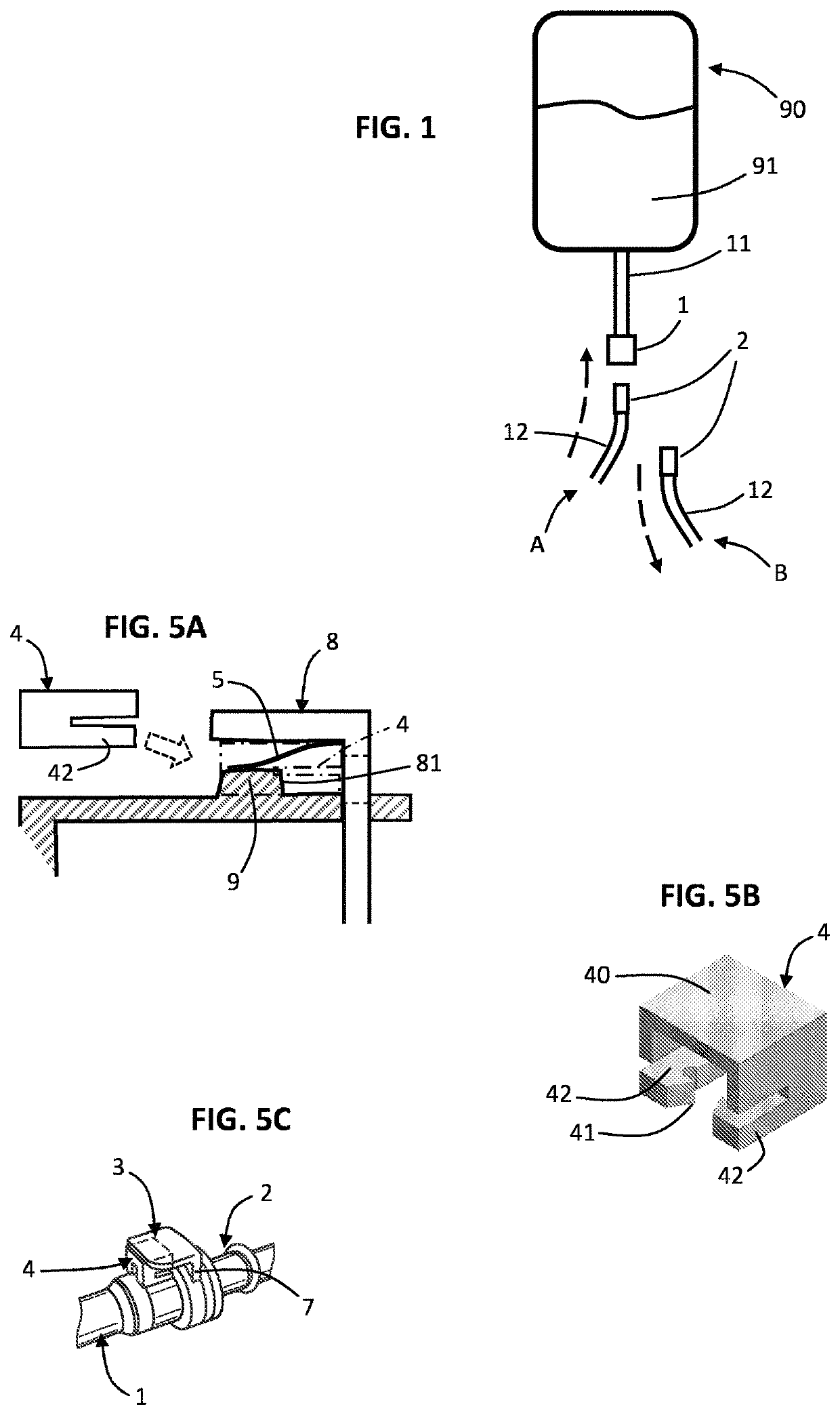
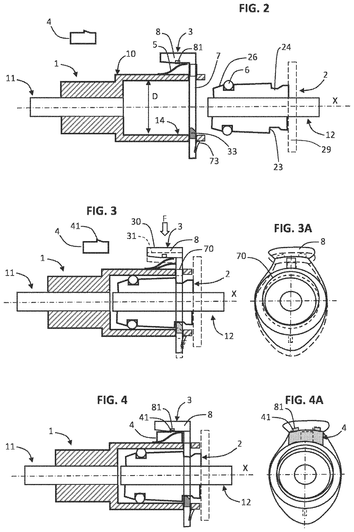
[0043]FIGS. 2, 3, 3A, 4 and 4A illustrate the fluid connection, comprising a female plug 1, and a male plug 2 intended to be inserted into the female plug, into the final coupling position represented in FIG. 3, in a coupling / decoupling movement parallel to the axial direction X.

[0044]The female plug 1 comprises an internal cylindrical receiving portion 14 of circular cross-section and of a diameter D which is slightly greater than the outside diameter of the male plug intended to be inserted into the female plug. In known manner, an O-ring 6 positioned in a groove of the male plug serves as a sealing means between the male plug and the female plug when they are in the coupling position as represented in FIGS. 3 and 4.

[0045]In addition, a movable primary locking device 3 is provided, in the form of a plate 7 arranged transversely to the axis X, with a manipulating portion 8 arranged perpendicular to said plate. In addition, the plate 7 comprises a substantially circular central hole...

second embodiment

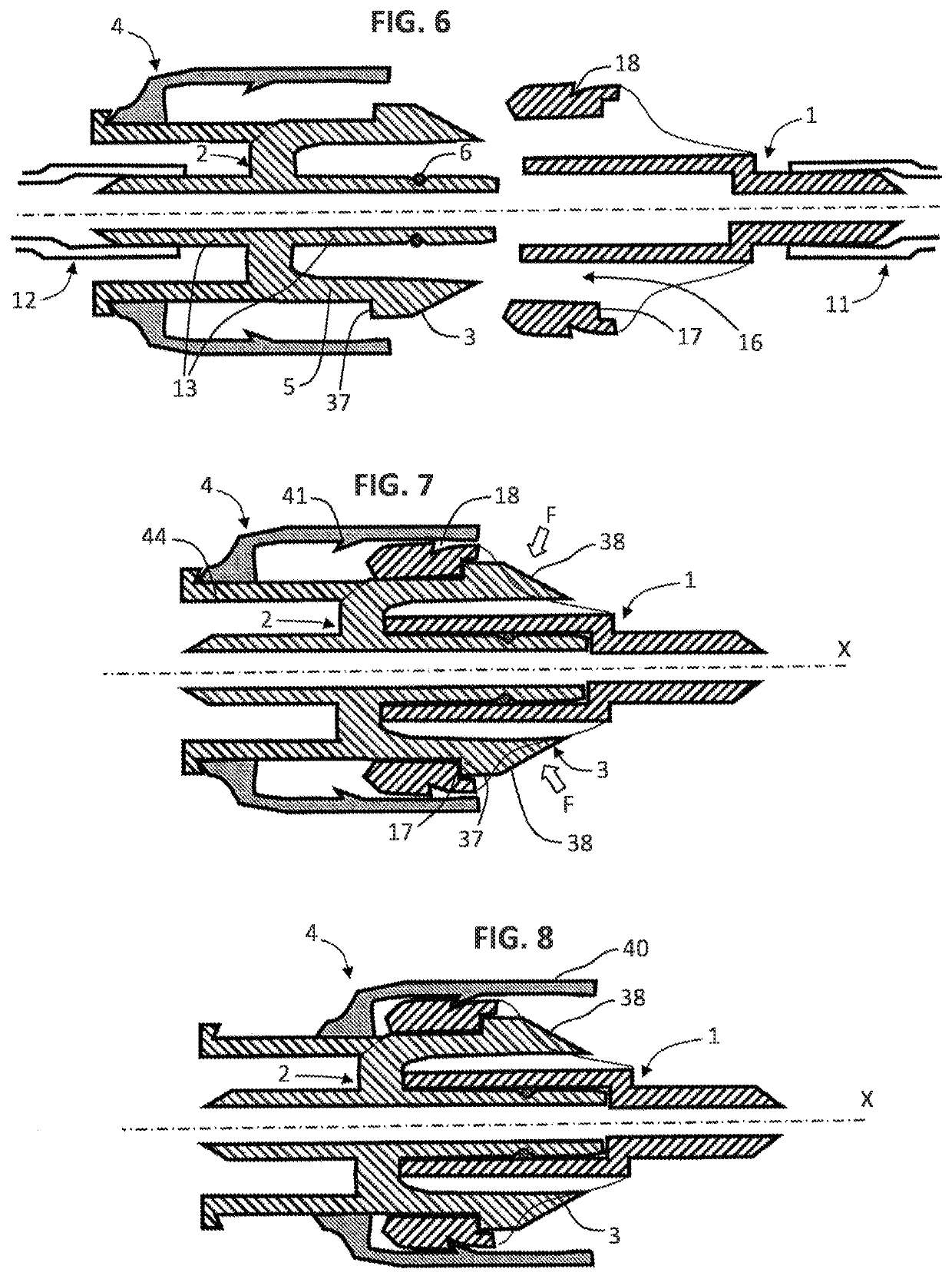
[0067]FIGS. 6, 7, and 8 illustrate the fluid connection, comprising a female plug 1 and a male plug 2, as above. In the figures, the female and male plugs are shown in a sectional view cut in a diametrical plane containing the main coupling and locking elements; the major portion of the circumference of the parts thereof is generally symmetrical about the axis X, except at the location of the main locking elements.

[0068]Advantageously, the general shape of the male and female plugs can be similar to the products in the SBL series available from the supplier ‘Value Plastics’, in other words having a generally elliptical cross-section with the largest radial dimension at the clips and a smaller radial dimension elsewhere.

[0069]The male plug 2 comprises a right circular cylindrical central portion 13 configured to be received in the female plug and configured to receive a hose or tube 12 forming the second conduit. In addition, the male plug comprises two diametrically opposite resilie...

third embodiment

[0076]FIGS. 9, 10, and 11 illustrate the fluid connection, comprising a female plug 1 and a male plug 2, as above.

[0077]As in the second embodiment, the primary locking device is in the form of two diametrically opposite clips arranged on the male plug. The operation of the primary locking device is quite similar to what was described for the second embodiment. However, the secondary lock 4 is arranged on the female plug 1, and has a rear annular portion 46 which surrounds a rear tubular area of the female plug; it also has at least two tabs 47 which extend axially, said tabs being adapted to come respectively between the inner forward portion 39 of each clip 3 and the outer cylindrical body 19 of the female plug, making it impossible for the clips to move from their locked position. The free space necessary for the unlocking movements is then occupied by the tabs 47, preventing any unlocking movement of the clips 3.

[0078]In addition, the rear tubular portion of the female plug comp...


PUM


Abstract

A fluid connection device (10) for connecting two fluid conduits (11, 12), includes a female plug (1), a male plug (2), intended to be inserted into the female plug into a final coupling position, a movable primary locking device (3), having a locked position (30) in which it prevents the male and female plugs from being released from the final coupling position, and a movable secondary latch (4) having an active position (40) designed to prevent the primary locking device (3) from being moved out of the locked position of same, whereby the fluid connection device can establish a permanent connection of the first and second conduits.

Description

[0001]The present invention relates to fluid connection devices, in particular for connecting together two fluid conduits.[0002]More particularly, the invention relates to a fluid connection device for interconnecting two fluid conduits, also called a connecting or coupling device. The fluid may be liquid, gaseous, or pasty, and the conduit may be a pipe or a conduit internal to a device.BACKROUND OF THE INVENTION[0003]It is known, in particular from document EP0462971, to use a fluid connection device to connect a first fluid conduit to a second fluid conduit, comprising:[0004]a female plug, made of plastic and joined to the first fluid conduit,[0005]a male plug, made of plastic, joined to the second fluid conduit, and intended for insertion into the female plug into a final coupling position, and[0006]a movable primary locking device, having a locked position in which it prevents the male and female plugs from being released from the final coupling position.[0007]However, in this ...

Claims


Application Information

Patent Timeline
IPC IPC(8): F16L37/098A61M39/10F16L37/084F16L21/08
CPCA61M39/1011F16L37/098F16L37/0841F16L37/0982F16L21/08A61M2039/1027F16L2201/10F16L2201/20
Inventor MENDYK, NICOLAS
Owner SARTORIUS STEDIM FMT SAS
Why Eureka
Try Eureka