Manufacturing method and manufacturing device for resin fan

a manufacturing method and resin technology, applied in the direction of machines/engines, liquid fuel engines, other domestic articles, etc., can solve the problems of difficult integral molding of fans, and achieve the effect of efficient resin manufacturing

Active Publication Date: 2020-02-25
MATSUDAKANAGATAKOGYO CO LTD
View PDF11 Cites 0 Cited by
  • Summary
  • Abstract
  • Description
  • Claims
  • Application Information

AI Technical Summary

Benefits of technology

As one of its advantages, the present invention can provide a method of and an apparatus for efficiently manufacturing a resin fan that is well suited for use in transporting a fluid, wherein the fan has the form in which the one circular plate has a large bend so formed as to be bent largely at the central opening portion and the central opening portion on the one circular plate is located away from the inner side of the other circular plate on the inner peripheral side of the one circular plate.

Problems solved by technology

In the inventions disclosed in Patent Documents 1 and 2, however, it has been found that it is difficult to integrally mold the fan, such as the one described above, that has the form in which it includes the first circular plate and the second circular plate, the first circular plate having a large bend at the central opening portion thereof and the central opening portion on the first circular plate being located away from the inner side of the second circular plate on the inner peripheral side of the first circular plate.

Method used


Image

  • Manufacturing method and manufacturing device for resin fan
  • Manufacturing method and manufacturing device for resin fan
  • Manufacturing method and manufacturing device for resin fan

Examples


Embodiment Construction

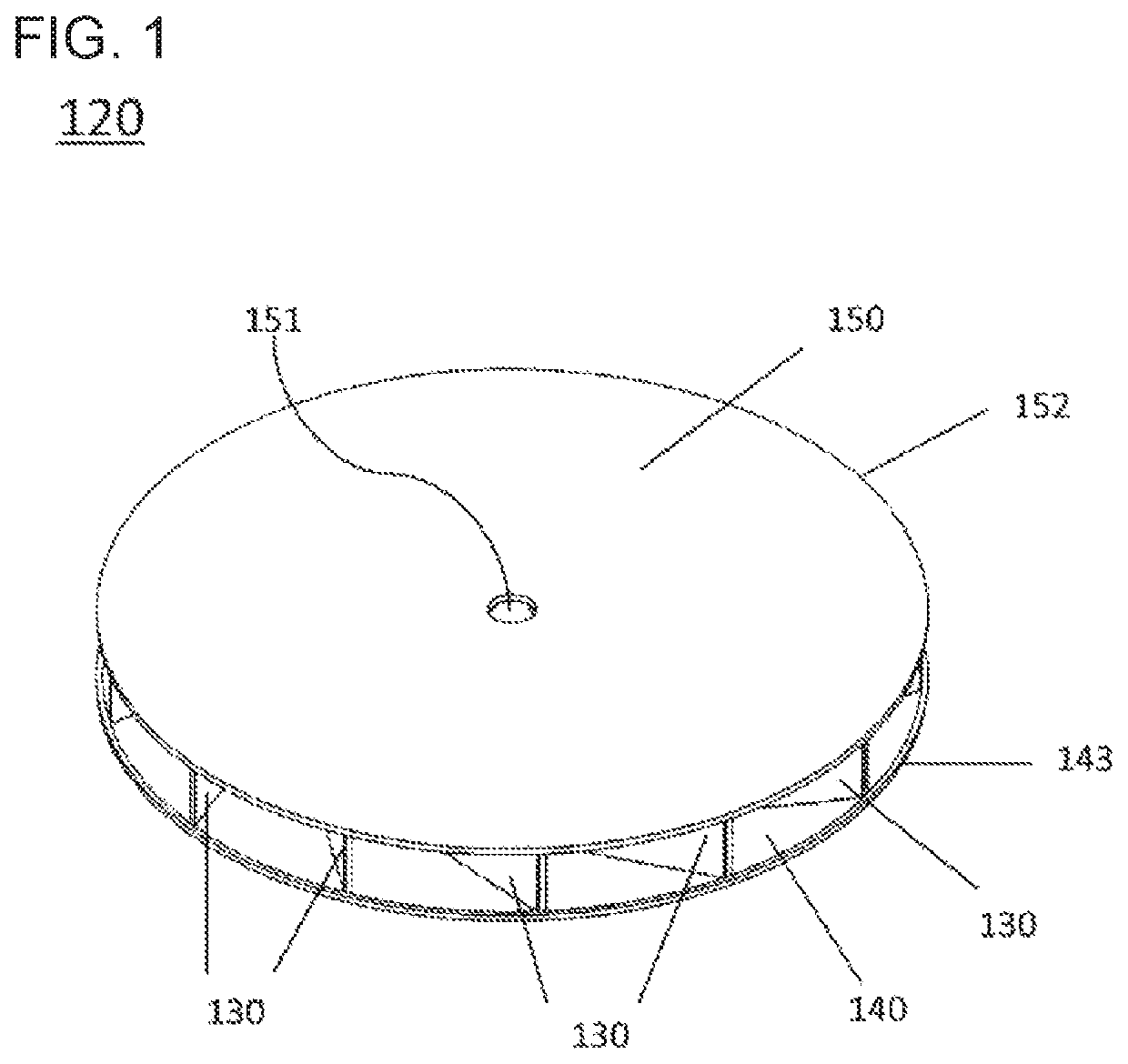
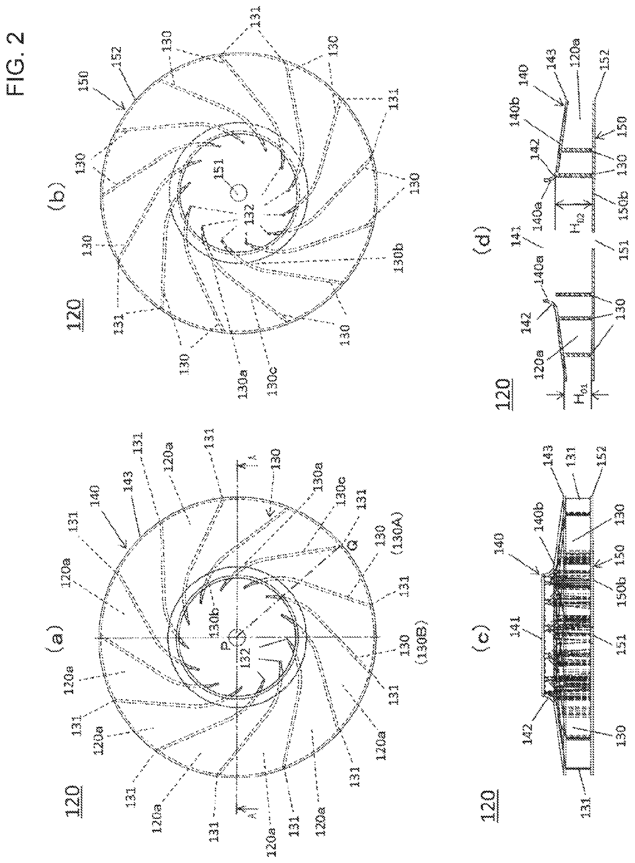
One example of one embodiment of the present invention is now described below by referring to the accompanying drawings. In this embodiment, a method of and an apparatus for manufacturing a resin fan with resin in the two-stage molding process will be described, wherein the fan has the form in which a multitude of blades arranged radially from the center are held securely between a first circular plate and a second circular plate aligned at the center with each other, the one circular plate having a large bend so formed as to be bent largely at the central opening portion and the central opening portion on said one circular plate being located away from the inner side of the other circular plate on the inner peripheral side of said one circular plate.

(Structure of a Fan to be Molded)

(1) As shown in FIG. 1 and FIG. 2, the resin fan 120 includes a multitude of blades 130, 130 arranged obliquely and radially from the center P and held securely between a first circular plate 140 and a s...


PUM

PropertyMeasurementUnit
heightaaaaaaaaaa
circumferenceaaaaaaaaaa
shapeaaaaaaaaaa

Abstract

A resin fan includes a semi-molded article in which a first circular plate and blades are integrated. While the semi-molded article is retained, a composite mold is moved to a secondary molding side, a second mold is put in a first position and a third mold is moved to the first position and inserted into the first mold. An intermediate part extends over the inner surface-side of a large-bend part, and causes the end of the third mold to engage with the first mold. Next, resin is poured into a secondary forming mold, and a second circular plate is integrally molded continuous with the blades of the semi-molded article, and a fan is molded. Together with the opening of the second mold and the composite mold, the third mold and the composite mold are opened, each of the molds is moved to a second position.

Description

BACKGROUNDTechnical FieldThe present invention relates to a method of and an apparatus for manufacturing a resin fan for use in transporting a fluid by means of a pump or the like wherein the resin fan can be molded with any suitable resin material by using a two-stage molding process.Description of the Prior ArtFor the conventional fan that is structured such that the blades arranged radially and held securely between the two circular plates are molded so that they are so formed as to be bent in the circumferential direction of the circular plates and a fluid introducing channel is formed between any two adjacent blades, the fluid introducing channel (blade) being wider (higher) on the inner peripheral side thereof and narrower (lower) on the outer peripheral side thereof, it has been found that it is difficult to mold the fan with resin in such that the circular plates and the blades can be united together into one unit by the integral molding process. In manufacturing the convent...

Claims


Application Information

Patent Timeline
Patent Type & Authority Patents(United States)
IPC IPC(8): B29C45/16B29C45/33F04D29/02B29C45/12F04D29/30F04D29/28B29C45/17B29C45/04B29L31/08
CPCF04D29/30B29C45/33B29C45/0441B29C45/12B29C45/1742F04D29/023F04D29/281B29C45/1635B29C2045/1637B29C2045/334B29C2045/336F05D2300/44F05D2300/603B29L2031/082
Inventor MATSUDA, MASAO
Owner MATSUDAKANAGATAKOGYO CO LTD
Why Eureka
Try Eureka