
Grommet

a technology of grommet and spherical head, which is applied in the direction of cable arrangement between relatively moving parts, electric/fluid circuit, electric cable installation, etc., and can solve problems such as difficulty in maintaining water tightness

Active Publication Date: 2020-02-25
YAZAKI CORP
View PDF12 Cites 2 Cited by
  • Summary
  • Abstract
  • Description
  • Claims
  • Application Information

AI Technical Summary

Benefits of technology

An object of the present invention is to provide a grommet which can maintain the water tightness in response to the inclination of the grommet.
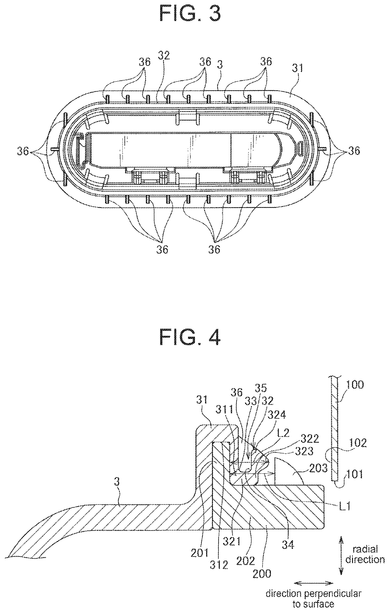
According to the grommet of the present invention described above, the substantially right-angled bending portion is formed between the first flange portion and the tubular portion. Thus, when the grommet is inclined with respect to the panel member, the angle of the bending portion changes, thereby absorbing the inclination. Consequently, the tubular portion itself is unlikely to be deformed, and thus the contact between the annular lip portion and the planar portion can be maintained. Thus, the water tightness can be maintained in response to the inclination.

Problems solved by technology

With the grommet described in JP'564, it is often difficult to maintain the water tightness when such inclination occurs in the grommet.

Method used


Image

  • Grommet
  • Grommet
  • Grommet

Examples


Embodiment Construction

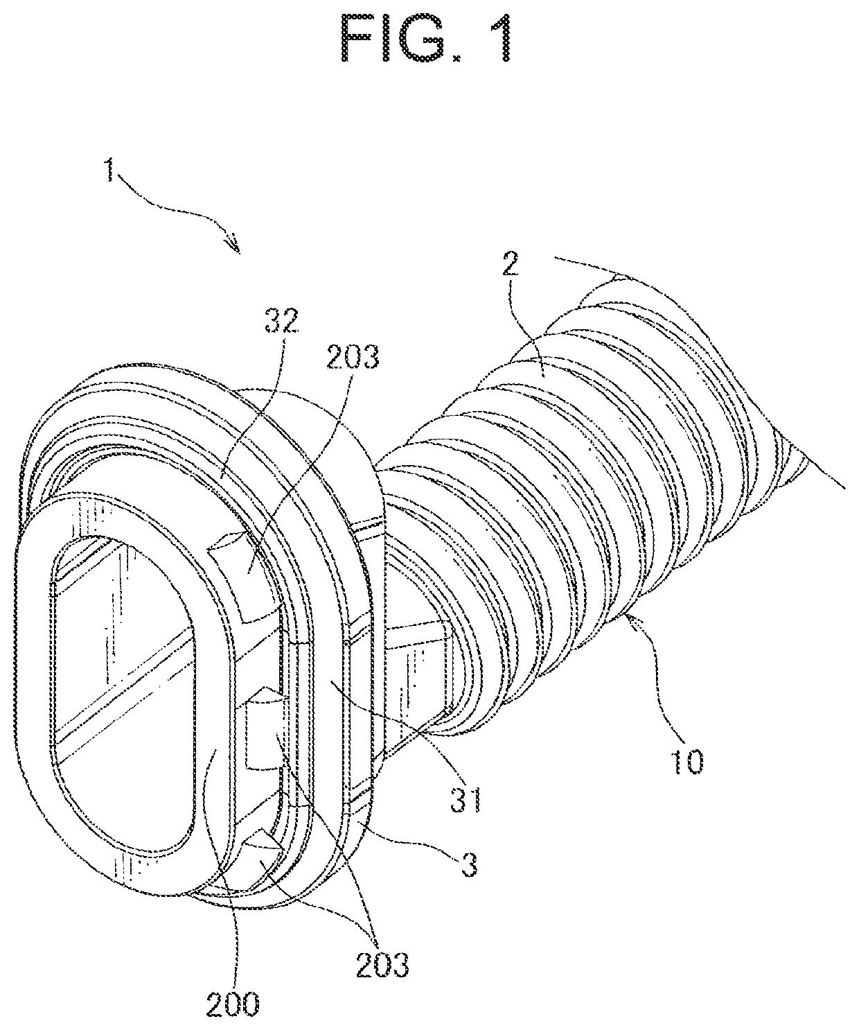
An embodiment of the present invention is hereinafter described in reference with the drawings. FIG. 1 is a perspective view of a grommet 1 according to the embodiment of the present invention. FIG. 2 is a plan view of the grommet 1. FIG. 3 is a plan view of an attachment section 3 of the grommet 1. FIG. 4 is a cross-sectional view of a portion of the grommet 1. FIG. 5 is a cross-sectional view of the grommet 1 attached to a panel member 100A. FIG. 6 is a cross-sectional view of the grommet 1 attached to another panel member 100B. FIG. 7 is a cross-sectional view of the grommet 1 being inclined with respect to the panel member 100A. FIG. 8 is a cross-sectional view of dies used to mold the attachment section 3.

As illustrated in FIGS. 1 to 3, the grommet 1 according to this embodiment is formed into a tubular shape so as to cover an electric wire and is configured to be attached to an attachment hole 101 of a panel member 100. The grommet 1 is configured to be mounted to a vehicle wi...


PUM


Abstract

A grommet which can maintain water tightness in response to inclination is provided. In an attachment section of the grommet, a substantially right-angled first bending portion is formed between a first flange portion and a tubular portion. Thus, when the attachment section is inclined with respect to a panel member, the first bending portion changes in angle, thereby absorbing the inclination, and thereby maintaining the contact between the annular lip portion and a planar portion. As a result, water tightness can be maintained in response to the inclination.

Description

CROSS REFERENCE TO RELATED APPLICATIONThe priority application Japanese Patent Application No. 2017-199458 upon which this patent application is based is hereby incorporated by reference.FIELD OF THE INVENTIONThe present invention relates to a grommet configured to be attached to an attachment hole of a panel member.BACKGROUND OF THE INVENTIONWhen mounting an electric wire to a vehicle door and such to feed electric power, a grommet may be used to protect the electric wire from water. For a vehicle with a sprung type back door, for example, one end of the grommet covering the electric wire may be attached to a vehicle body-side panel member, while the other end of the grommet may be attached to a door-side panel member, in the vicinity of a hinged portion of the back door.In a known example of such grommet, a flange portion that faces the panel member and an annular lip portion that contacts with an opening edge (planar portion) of the attachment hole, are arranged to abut each othe...

Claims


Application Information

Patent Timeline
Patent Type & Authority Patents(United States)
IPC IPC(8): H02G3/22B60R16/02H02G3/04H02G3/06
CPCB60R16/0222H02G3/0691H02G3/22H02G3/0468H02G3/28H02G11/00
Inventor OGAWA, MASAYOSHIYOKOYAMA, SATOSHIIKEDA, SHINICHI
Owner YAZAKI CORP
Learn More