Water-proof structure

A structure and watertight technology, applied in the field of waterproof structure of the drive device, can solve the problems of complicated manufacture, immersion, complicated structure, etc., and achieve the effect of preventing falling off

Inactive Publication Date: 2007-05-30
有限会社一色制作所
View PDF1 Cites 0 Cited by
  • Summary
  • Abstract
  • Description
  • Claims
  • Application Information

AI Technical Summary

Problems solved by technology

[0005] With regard to the above-mentioned Patent Document 1, the vibrator is protected in a watertight state by covering the vibrator with a bag-shaped body formed of a waterproof stretchable material, and a machine that can be used in a water environment is made, but the above-mentioned The covering of the vibrator is to close the opening by using the opening with a diameter that can be closely fitted to make it closely fit. For the use situation, there is an opening of the above-mentioned bag-shaped body that overcomes the tightness of the opening. In the case of opening due to adhesive force, there is a problem that water drops enter the vibrator from the above-mentioned opened part.
[0006] With regard to the above-mentioned Patent Document 2, it is possible to cover the battery case with a waterproof case to prevent water leakage by rolling up the open end of the waterproof case and inserting it into a two-stage convex groove formed on the outer surface of the battery case. , for the battery box in this solution, in terms of usage conditions, the cooperation between the above-mentioned two-section rib-shaped groove and the above-mentioned kneaded and embedded opening end is released, and the above-mentioned waterproof casing resists the movement of the opening end of the above-mentioned waterproof casing. Closed and opened, and there is a bad situation where water drops enter the battery box from the opened part
[0007] In addition, if the above-mentioned battery storage portion and the operation button portion are formed with a waterproof structure without using the above-mentioned case, the configuration becomes complicated. In addition, since the above-mentioned waterproof portion must be precisely formed, it is complicated to manufacture, and at the same time, there is a need for expensive manufacturing. bad condition

Method used


Image

  • Water-proof structure
  • Water-proof structure
  • Water-proof structure

Examples


Embodiment Construction

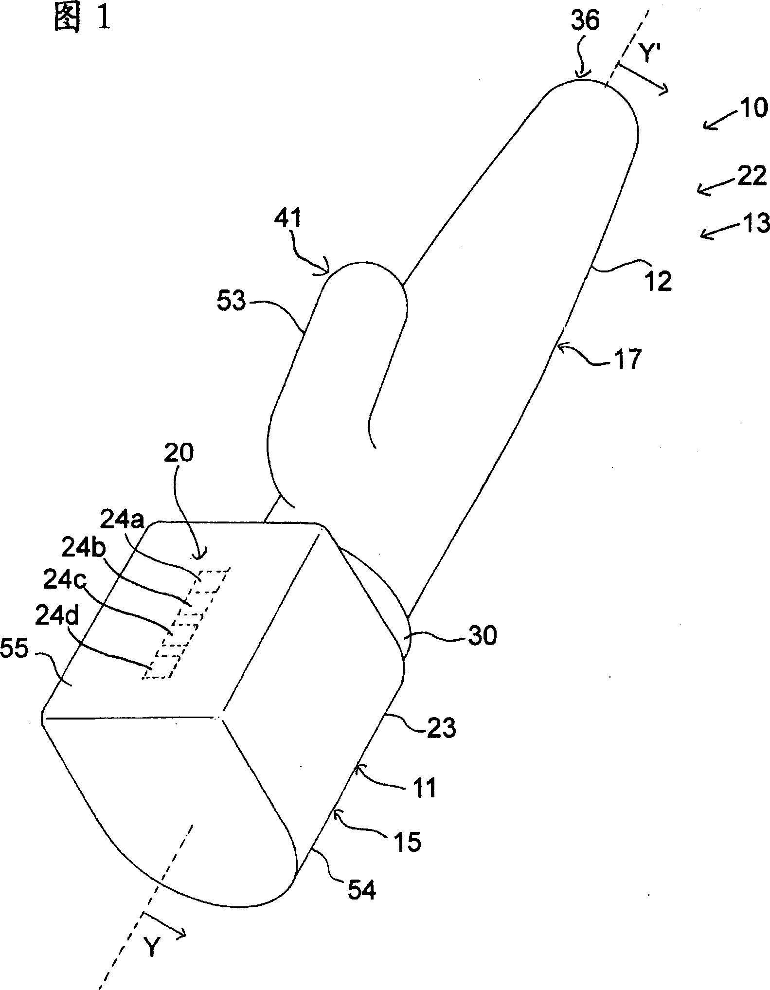
[0101] Hereinafter, the waterproof structure 10 of the present invention will be described in detail based on the embodiments shown in the drawings.

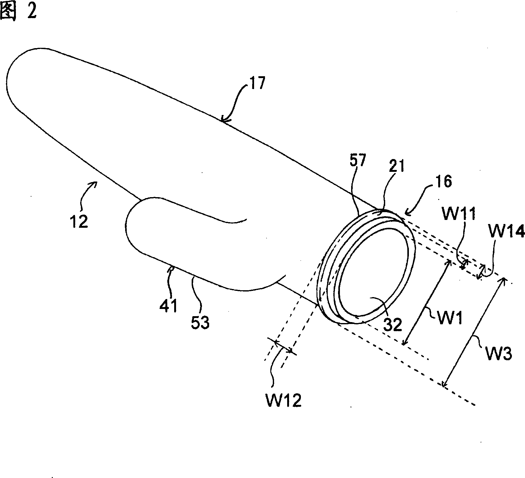
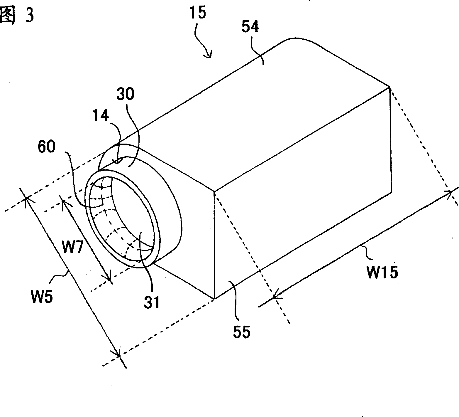
[0102]The waterproof structure 10 of this embodiment, as shown in FIG. The waterproof structure 10 of the driving device 13 formed by the formed driving part 12, the above-mentioned waterproof structure 10 has: as shown in Figure 1 and Figure 3, an opening 31 is formed on one end, and is formed to cover the above-mentioned power supply in a watertight state. 1 and 2, an opening 32 is formed at one end and is formed to cover the drive unit 12 in a watertight state. As shown in FIG. 4, on one end of the above-mentioned power supply part 11, there is provided a support tube part 18 protrudingly formed to the side of the above-mentioned driving part 12, and a support tube part 18 is provided on the outside in the radial direction of the above-mentioned support tube part 18 at a predetermined interval. 7, the opening edge 16 of the ...


PUM


Abstract

A waterproofing structure which can protect a drive device in the water-tight state and which can establish the water-tight state without raising the manufacturing cost. A waterproofing structure 10 for a drive device 13 including: a power supply unit 11; and a drive unit 12 formed to protrude from one end of the power supply unit 11 and to be operated with an electric power supplied from the power supply unit 11. The waterproofing structure 10 comprises: a power supply unit cover 15 formed to have an opening at its one end and to cover the power supply unit 11 in the water-tight state; and a drive unit cover 17 formed to have an opening at its one end and to cover the drive unit 12 in the water-tight state. The power supply unit 11 includes at its one end a supporting cylinder unit 18 formed to protrude to the side of the drive unit 12, and a protecting cylinder unit 19 formed outside of the diameter of and at a predetermined spacing size from the supporting cylinder unit 18. The drive unit cover 17 has its opening edge portion 16 fitted in the water-tight state between the supporting cylinder unit 18 and the protecting cylinder unit 19 so that the opening circumferential edge portion 27 of the drive unit cover 17 and the protecting cylinder unit 19 can be covered in the water-tight state with the opening edge portion 14 of the power supply unit cover 15.

Description

technical field [0001] The present invention relates to a waterproof structure of a driving device that can be used in bathrooms, water wading environments, etc., and particularly relates to a waterproof structure that can protect the matching part of the driving device in a watertight state and can form the above watertight state without increasing manufacturing costs. Background technique [0002] In the past, the driving devices of electric toys, massage machines, etc. used in bathrooms, outdoors, or environments where liquids adhered were formed by electronic devices such as battery boxes, motors, or controller switches. In order to avoid failures caused by air, there are waterproof devices tightly covered by a waterproof case (Patent Document 1, Patent Document 2). [0003] Patent Document 1: JP-A-2005-237911 [0004] Patent Document 2: Shi Gong No. 06-17516 [0005] With regard to the above-mentioned Patent Document 1, the vibrator is protected in a watertight state ...

Claims


Application Information

Patent Timeline
Patent Type & Authority Applications(China)
IPC IPC(8): A63H19/22H01M2/02H02K5/12H01H9/04H01M50/24
CPCA61H23/0254A61H2201/0153A61H19/34A61H19/44A61H2201/0111A61H2201/0115
Inventor 一色利男
Owner 有限会社一色制作所
Why Eureka
Try Eureka