
Lockable wheel actuator disengagement system on an aircraft landing gear

a technology of locking wheel actuator and actuator, which is applied in the direction of mechanical equipment, clutches, transportation and packaging, etc., can solve the problem of the risk of the driving system remaining mechanically coupled with the wheel

Active Publication Date: 2020-03-17
SAFRAN LANDING SYSTEMS
View PDF11 Cites 0 Cited by
  • Summary
  • Abstract
  • Description
  • Claims
  • Application Information

AI Technical Summary

Benefits of technology

The solution effectively secures the driving system in a safety position, preventing interference with the wheel and reducing the risk of accidental clutching, even in the event of manoeuvring system failures, thus enhancing safety and operational reliability.

Problems solved by technology

It has been found that, in case of a breakdown of the manoeuvring system which controls the passage between the declutched and clutched positions, there is a risk of the driving system remaining mechanically coupled with the wheel.

Method used


Image

  • Lockable wheel actuator disengagement system on an aircraft landing gear
  • Lockable wheel actuator disengagement system on an aircraft landing gear
  • Lockable wheel actuator disengagement system on an aircraft landing gear

Examples


Embodiment Construction

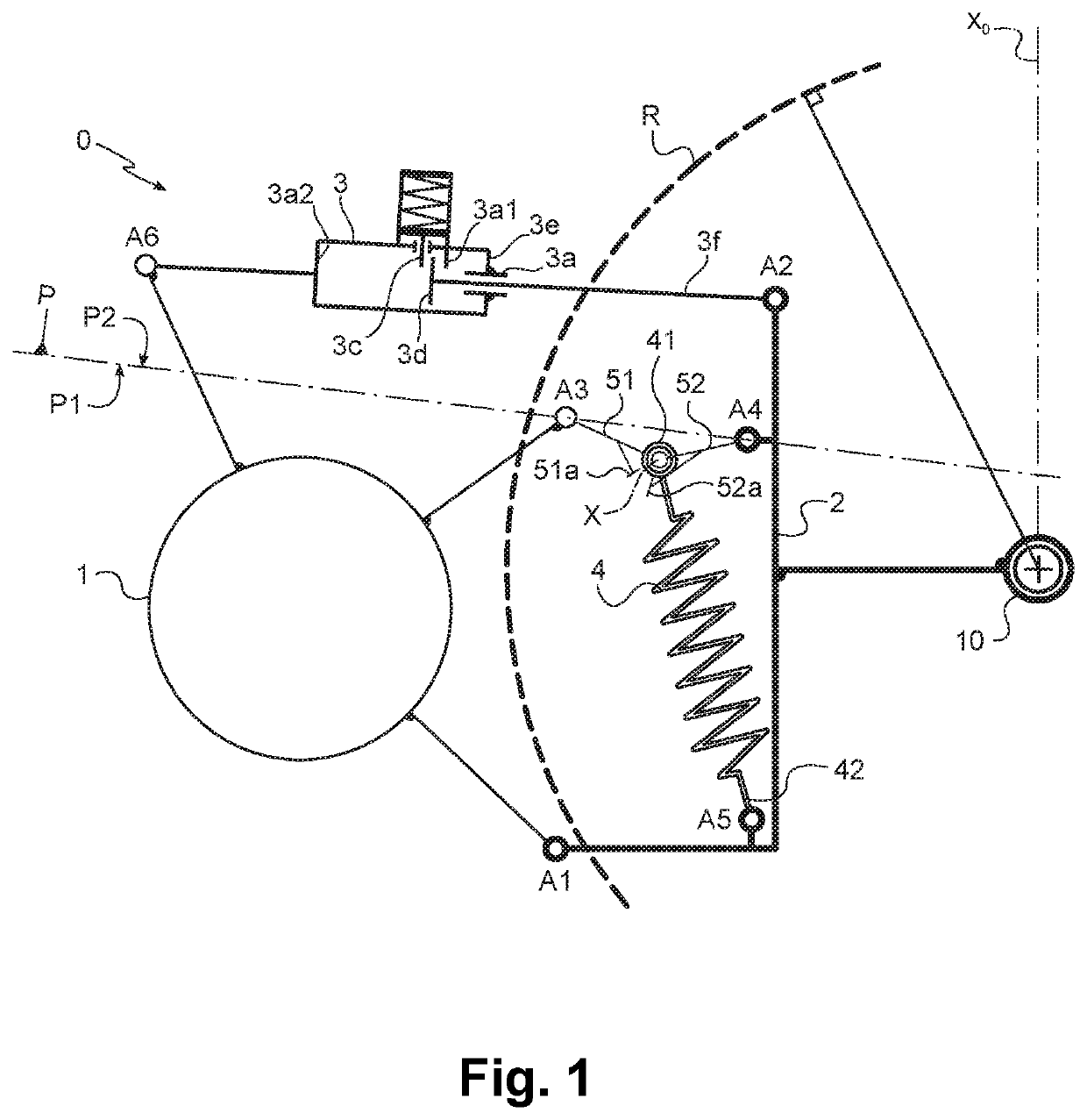
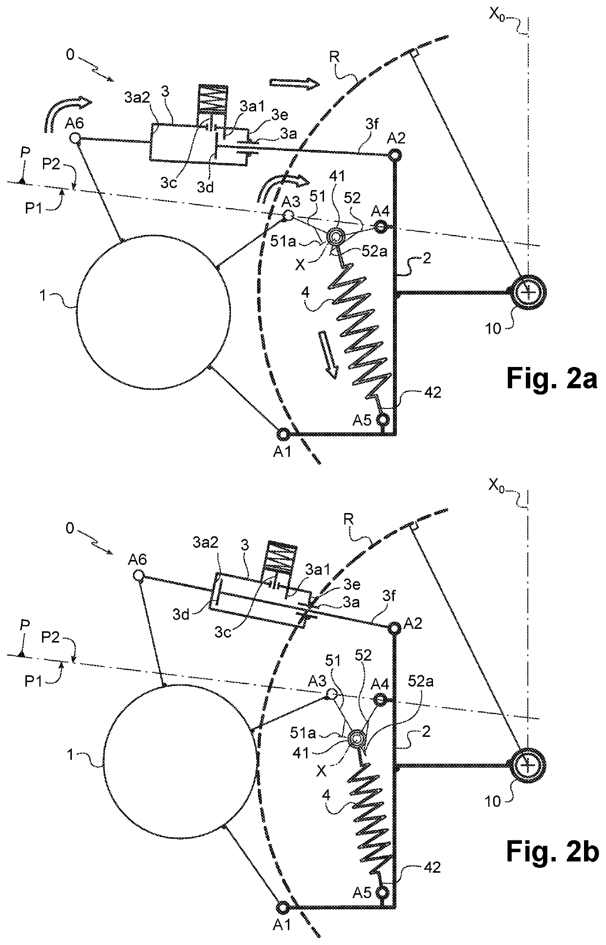
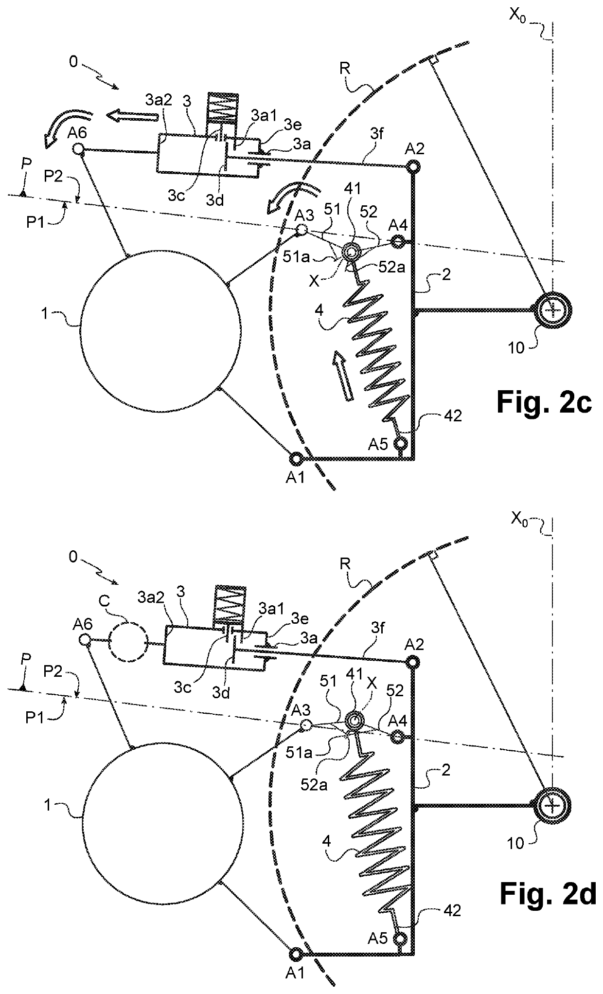
[0050]The invention relates to a landing gear 0 for aircraft. This landing gear 0 is partially illustrated in FIGS. 1, 2a, 2b, 2c, 2d and 3 and comprises a leg extending along a longitudinal axis X0 of extension of the leg. For reasons of clarity, the leg is not illustrated and only its longitudinal axis X0 is schematically represented.

[0051]The landing gear 0 is linked to a supporting structure of the aircraft via its leg.

[0052]A terminal end of this leg bears at least one axle 10 about which at least one wheel R for the taxiing of the aircraft on the ground is mounted to rotate. For reasons of clarity, only portions of the axle 10 and of the wheel R are represented.

[0053]The wheel R is driven in rotation by a driving system 1 which can be a motor such as a rotary electric motor capable of transmitting a driving torque for the wheel R when it is in clutched position as in FIG. 2b.

[0054]The wheel R can be fixedly linked to a driving crown wheel and, in this case, the driving system...


PUM


Abstract

A landing gear (0) for an aircraft comprising a wheel (R), a system (1) for rotationally driving the wheel that is mobile between a clutched position and a safety position by passing through a declutched position, and a manoeuvring system (3) to displace the driving system (1) between its declutched and clutched positions. The gear comprises an elastic return (4) for returning the driving system (1) to its safety position and first and second abutments (51a, 52a) that are separated as long as the driving system (1) is away from its safety position and in contact with one another when the driving system (1) is in safety position. The first and second abutments (51a, 52a) oppose the passing of the driving system (1) from its safety position to its declutched position when the abutments are in contact with one another.

Description

[0001]The invention relates to the general field of landing gears for aircraft equipped with a system for rotationally driving the wheel of the landing gear.BACKGROUND OF THE INVENTION[0002]The patent document FR3011531 A1 for example teaches of a landing gear for aircraft comprising:[0003]at least one wheel for the taxiing of the aircraft on the ground;[0004]a system for rotationally driving the wheel that is mobile between a clutched position with respect to the wheel and a safety position by passing through a declutched position with respect to the wheel;[0005]a manoeuvring system linked to the driving system to displace it between its declutched and clutched positions.[0006]It has been found that, in case of a breakdown of the manoeuvring system which controls the passage between the declutched and clutched positions, there is a risk of the driving system remaining mechanically coupled with the wheel. It is consequently desirable to provide a solution that makes it possible, in ...

Claims


Application Information

Patent Timeline
Patent Type & Authority Patents(United States)
IPC IPC(8): B64C25/40F16D28/00F16D25/00
CPCB64C25/405F16D28/00F16D25/00Y02T50/823B64C25/34B64C25/62Y02T50/80
Inventor BELLENGER, VINCENT
Owner SAFRAN LANDING SYSTEMS
Learn More