Derivation of disparity motion vector, 3D video coding and decoding using such derivation

a motion vector and motion vector technology, applied in the field of image processing in three dimensions, can solve the problems of high cost associated with mvc coding, limited to views which necessarily contain texture and depth components, and achieve the effect of more reliable and accura

Active Publication Date: 2020-03-17
ORANGE SA (FR)
View PDF18 Cites 1 Cited by
  • Summary
  • Abstract
  • Description
  • Claims
  • Application Information

AI Technical Summary

Benefits of technology

[0044]Such a provision proves particularly advantageous in the case where the disparity motion vector is intended to be added to a set of motion vectors likely to be selected to predict the motion of a current image that has, for example, a format of MVV or MVD type, because the prediction is rendered more reliable and more accurate. The result thereof is a more efficient coding and decoding of the current image.
[0045]Such a provision proves also advantageous in the case where the disparity motion vector obtained from the derivation method is used for the prediction of the residual of the current block of a view of a multi-view image, rendering this prediction also more reliable and more accurate.
[0053]Such a provision has the advantage of saving on computation and memory resources in the coder and in the decoder.
[0058]Such a second variant makes it possible to speed up the obtaining of the final disparity motion vector by the deletion, in at least one list of disparity motion vectors considered, disparity motion vectors for which the amplitude and the orientation are equal or similar, the function then being applied to a smaller number of disparity vectors.
[0060]Such a third variant makes it possible to further speed up the obtaining of the final disparity motion vector, since it is applied to at least one list of disparity motion vectors whose size has previously been reduced.

Problems solved by technology

However, the cost associated with the MVC coding is high, particularly when the number of points of view is great.
The drawback with this first method is that it is costly in computation and memory terms.
The drawback of this second derivation method is that the first disparity motion vector which, according to the case, is found or read, is maybe not the one which will optimize the efficiency of the coding or of the decoding of the current block.
The drawback of such a derivation method is that it is limited to views which necessarily contain texture and depth components.
Furthermore, it does not take into account other types of disparity motion vectors, such as, for example, disparity motion vectors used to derive temporal motion vectors.
The drawback of such a derivation method is that it is limited to views which necessarily contain texture and depth components.
Although the selection of the final disparity motion vector is obtained from a plurality of disparity motion vectors contained in one or two lists, contrary to the second derivation method which retains only a single disparity motion vector, the drawback of this fifth method is that the first list of SDVC vectors, just like the second list of TDVC vectors, contains only disparity motion vectors which are used in the context of an interview prediction.
The selection of the disparity motion vector according to this fifth method is not therefore optimal.

Method used


Image

  • Derivation of disparity motion vector, 3D video coding and decoding using such derivation
  • Derivation of disparity motion vector, 3D video coding and decoding using such derivation
  • Derivation of disparity motion vector, 3D video coding and decoding using such derivation

Examples


Embodiment Construction

[0088]An embodiment of the invention will now be described, in which the disparity motion vector derivation method according to the invention is for example intended to be implemented in the case of the coding / decoding of an image or of a sequence of images according to a binary stream close to that that is obtained by a coding / decoding conforming, for example, to the 3D-HEVC standard currently being prepared.

[0089]To this end, the image or images considered may, for example, be in MVV or MVD format.

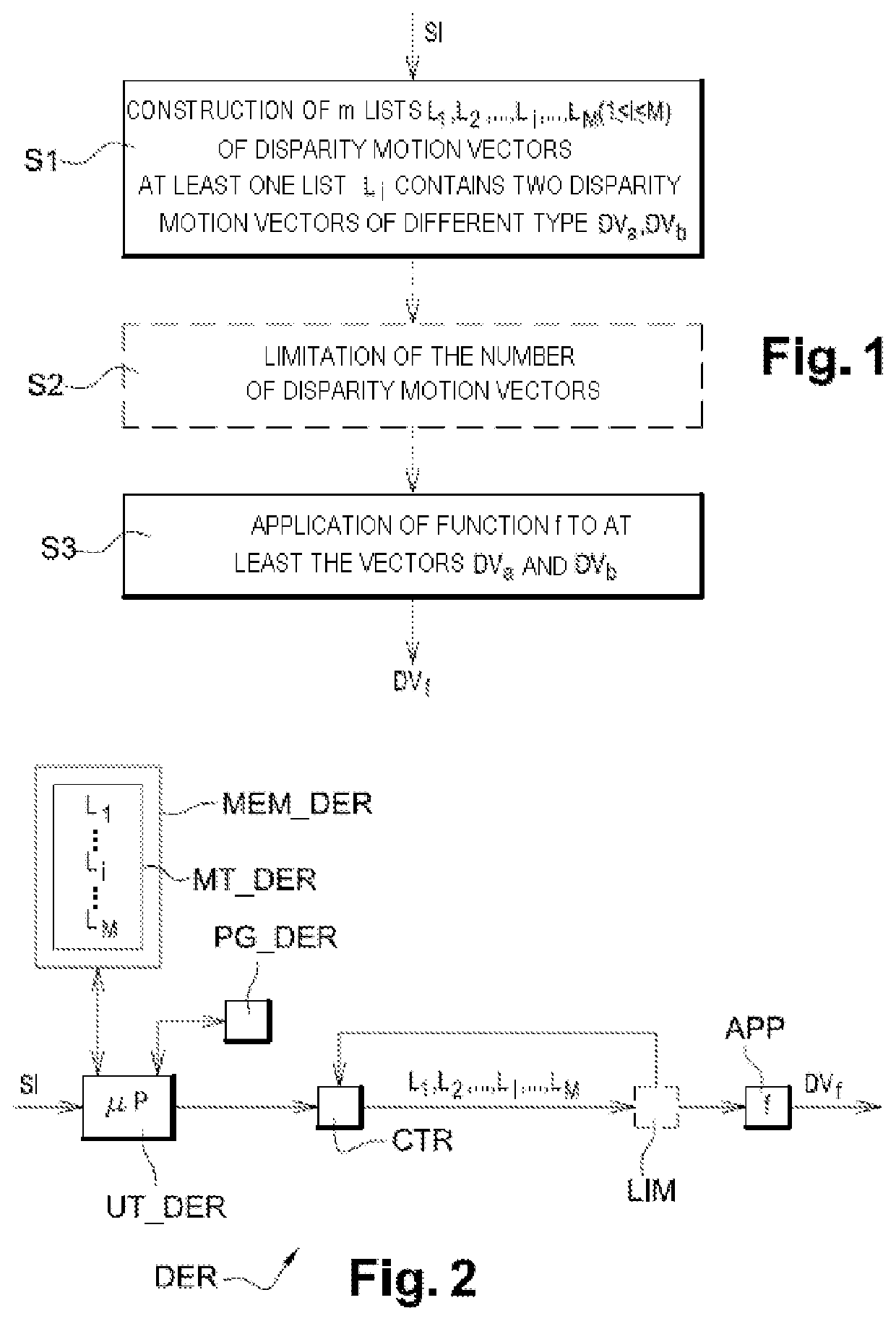
[0090]In this embodiment, the derivation method according to the invention is for example implemented by software or hardware by modifications to a derivation device contained in a coder / decoder initially conforming to the 3D-HEVC standard. The derivation method according to the invention is represented in the form of an algorithm comprising steps S1 to S3 as represented in FIG. 1.

[0091]According to the embodiment of the invention, the derivation method according to the invention is impl...


PUM


Abstract

A method is provided for decoding a current image having at least two views which are respectively representative of a same scene. The decoding method includes derivation of a disparity motion vector and, during the derivation: constructing at least one list of disparity motion vectors, in which at least two disparity motion vectors have been obtained respectively according to two different estimation methods; and applying a function to the at least two disparity motion vectors of the list. The method is applicable, for example, to a current image Ik of an MVV or MVD type.

Description

CROSS-REFERENCE TO RELATED APPLICATIONS[0001]This Application is a Section 371 National Stage Application of International Application No. PCT / FR2014 / 050384, filed Feb. 24, 2014, the content of which is incorporated herein by reference in its entirety, and published as WO 2014 / 131975 on Sep. 4, 2014, not in English.FIELD OF THE INVENTION[0002]The present invention relates generally to the field of image processing in three dimensions (3D), and more particularly to the coding and decoding of 3D digital images and of sequences of 3D digital images. It relates in particular, but not exclusively, to 3D video applications which implement a coding / decoding of images from different cameras.[0003]The invention can notably, but not exclusively, be applied to the video coding implemented in the current AVC and HEVC video coders and their extensions (MVC, 3D-AVC, MV-HEVC, 3D-HEVC, etc), and to the corresponding decoding.BACKGROUND OF THE INVENTION[0004]A 3D representation of a video can be obt...

Claims


Application Information

Patent Timeline
Patent Type & Authority Patents(United States)
IPC IPC(8): H04N19/597H04N13/00H04N13/128H04N13/178H04N13/122H04N19/527H04N19/56H04N19/513
CPCH04N13/128H04N13/178H04N19/597H04N13/122H04N19/521H04N19/56H04N19/527H04N2013/0081
Inventor MORA, ELIE GABRIELJUNG, JOEL
Owner ORANGE SA (FR)
Why Eureka
Try Eureka