System state prediction

a technology of system state and prediction method, applied in the field of system state prediction, can solve the problems of no sensor data, difficult scaling or applicable to fleets, and difficult to place sensors for direct temperature measurement at pole shoes in production devices, etc., to achieve accurate and reliable prediction of system behaviour and life time

Inactive Publication Date: 2019-01-24
SIEMENS AG
View PDF3 Cites 1 Cited by
  • Summary
  • Abstract
  • Description
  • Claims
  • Application Information

AI Technical Summary

Benefits of technology

[0011]The second method allows to use the lessons learned on system A to make an improved forecast for system B. While training the prediction fusion operator on system A may require a lot of effort in terms of training time or provision of training data, transfer of the prediction fusion operator to system B can be done with little effort. The prediction fusion operator can be small in size. Key information of a corresponding neural network may routinely amount to a few 100 kByte. This allows frequent updating of the prediction fusion operator, such as to enforce propagation of newly learned system behaviour on system A to system B.
[0019]Embodiments of the invention may provide model based condition monitoring not only for a few examples with specific simulation but transferable for other configurations within the same characteristics class. With condition based monitoring of this additional information also additional services regarding stress, life time prediction and product evolution for coming generation design may be possible. Holistic monitoring models may be achieved for product portfolio, compensating weaknesses of separated models and getting more accurate and reliable prediction of system behaviour and life time.

Problems solved by technology

Nevertheless regarding a product portfolio, there are locations of interest for monitoring and control, especially critical hot spots, where no measurement, thus no sensor data, is available.
Since the pole shoes are part of the rotor side, sensors for direct temperature measurements at the pole shoes cannot be placed in production devices due to high associated cost.
But the development of such calculation modules is based on detailed 3D geometry models of specific product components, effort intensive and therefore hard to scale or applicable for fleets with high number of individual configured product types (e.g. electrical motors) with individual physical behaviour and individual environmental conditions in the field.

Method used


Image

  • System state prediction
  • System state prediction
  • System state prediction

Examples


Embodiment Construction

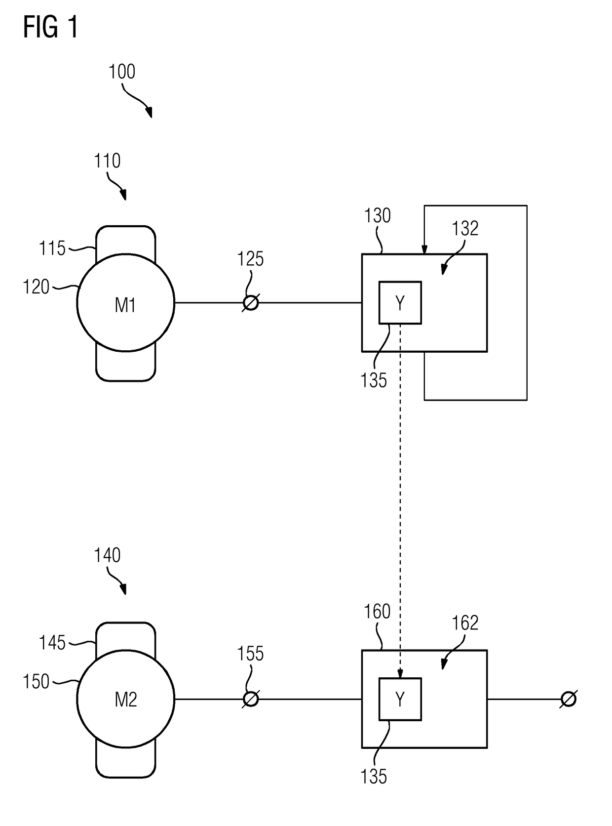
[0027]FIG. 1 shows a schematic depiction 100 of two similar exemplary physical systems. A first system 110 and a second system 140 are each represented by exemplary asynchronous electric motors, although embodiments of the invention are not limited to electric machinery. The electric motor 110, 140 may be large drive motors for elevators, belt conveyors or sewage pumps, with a power declaration in the range of up to several 100 kW. The first motor 110 comprises a first stator 115 and a first rotor 120 and the second motor 140 comprises a second stator 145 and a second rotor 150.

[0028]The motors 110, 140 may be mass producible items which may come in different product lines and power declarations. The product lines may differ in the number of pole pairs the motor 110, 140 has. The motors 110, 140 are considered similar as long as they stem from the same motor design and differ only in product line and / or power declaration (i.e. size). When a motor 110, 140 is connected to a power sup...


PUM


Abstract

A method includes the following steps: observing a first state vector including state variables in a physical system A; determining a first prediction vector based on the first state vector, with a data driven model for system A; determining a second prediction vector based on the first state vector, with a physics based model for system A; training a prediction fusion operator to determine a third prediction vector based on the first and second prediction vectors; validating the prediction fusion operator on the third prediction vector and another first state vector, the other first state vector concerning the same time as the third prediction vector.

Description

CROSS-REFERENCE TO RELATED APPLICATIONS[0001]This application claims priority to European application No. EP 17182315.6 having a filing date of Jul. 20, 2017, the entire contents of which are hereby incorporated by reference.FIELD OF TECHNOLOGY[0002]The following concerns a technique for predicting system behaviour of a physical system. More specifically, the following concerns the transfer of parameter prediction between similar systems.BACKGROUND[0003]To improve business intelligence and smart services, more and more sensors are employed to pick up data from systems that need observation. Nevertheless regarding a product portfolio, there are locations of interest for monitoring and control, especially critical hot spots, where no measurement, thus no sensor data, is available. Recently mathematical model based approaches using physical behaviour calculation of the underlying process in parallel to operation linked with current system conditions, are able to generate additional inf...

Claims


Application Information

Patent Timeline
Patent Type & Authority Applications(United States)
IPC IPC(8): G06F17/16G06N7/08G06N3/08
CPCG06F17/16G06N7/08G06N3/08H02P29/66G06F2119/04G06F30/20G05B17/02
Inventor ALLMARAS, MORITZBERGS, CHRISTOPHHARTMANN, DIRKOBST, BIRGIT
Owner SIEMENS AG
Why Eureka
Try Eureka