Bracket for on-vehicle camera

a technology for on-vehicle cameras and brackets, which is applied in the direction of vehicle components, optical viewing, transportation and packaging, etc., can solve the problems of likely external force on-vehicle cameras, and achieve the effect of facilitating breakag

Active Publication Date: 2020-03-24
FALTEC CO LTD
View PDF7 Cites 1 Cited by
  • Summary
  • Abstract
  • Description
  • Claims
  • Application Information

AI Technical Summary

Benefits of technology

[0007]The disclosure is directed to a bracket for an on-vehicle camera which is capable of protecting both a hitting object and a portion of a vehicle body where the on-vehicle camera is fixed.
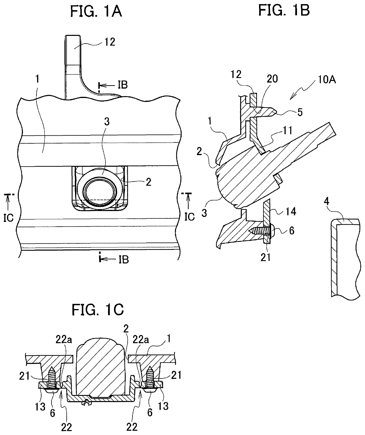
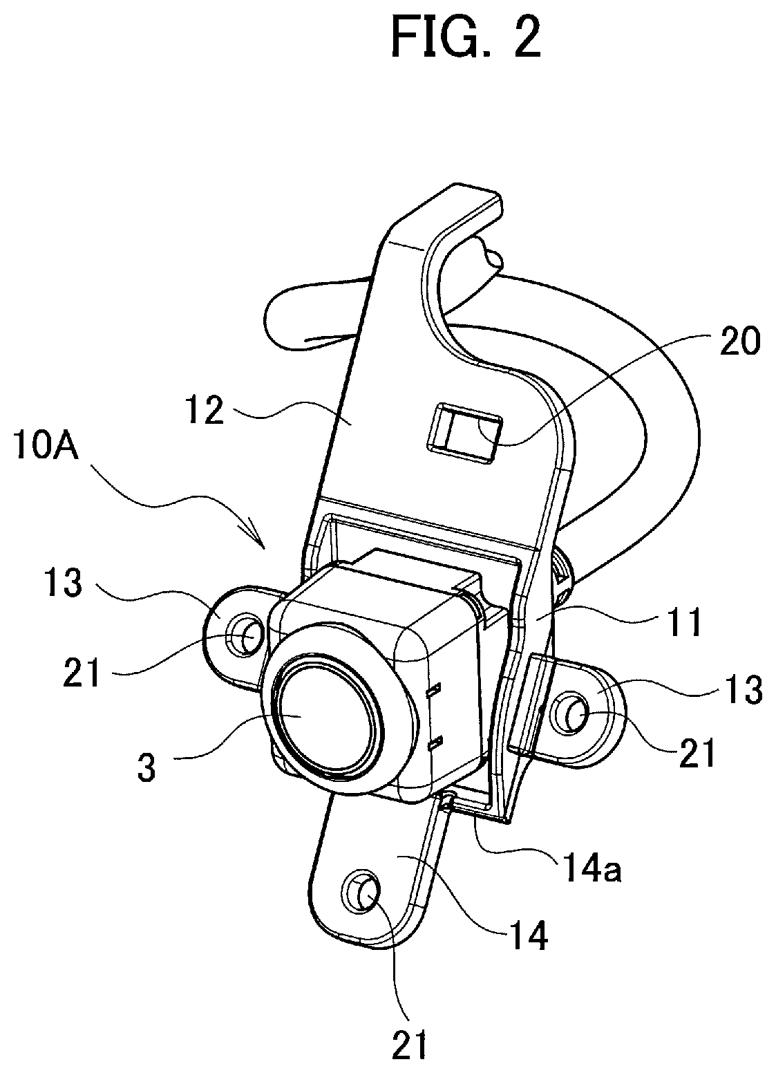
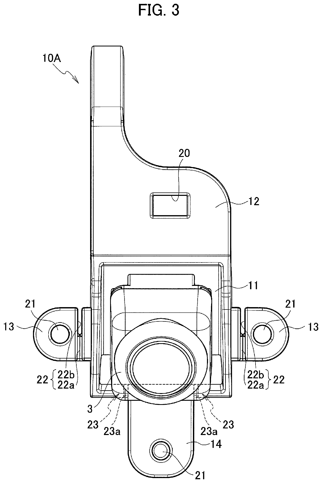
[0008]A bracket for an on-vehicle camera in accordance with some embodiments includes: a camera fixing portion to which the on-vehicle camera is fixed; at least one vehicle-mount fixing portion provided integrally with the camera fixing portion and configured to be fixed to a vehicle body; and at least one weak portion arranged at a position at which the camera fixing portion is separable from the at least one vehicle-mount fixing portion by breakage of the at least one weak portion, the at least one weak portion being breakable more easily than another part of the bracket.
[0009]According to the above configuration, when a hitting object hits an on-vehicle camera and an external force is exerted on the on-vehicle camera, the at least one weak portion is broken, and the on-vehicle camera comes off the vehicle body side. Thus, there is no possibility of giving a major damage to the hitting object and the portion of the vehicle body where the on-vehicle camera is fixed, and it is possible to protect both the hitting object and the portion of the vehicle body where the on-vehicle camera is fixed.

Problems solved by technology

Accordingly, an on-vehicle camera is likely to receive external force by factors such as hitting other members.
When a hitting object hits the on-vehicle camera, the bracket for an on-vehicle camera described above may allow damage in some cases to the hitting object or the portion of the vehicle body (such as window glass) where the on-vehicle camera is fixed.

Method used


Image

  • Bracket for on-vehicle camera
  • Bracket for on-vehicle camera
  • Bracket for on-vehicle camera

Examples


Embodiment Construction

[0023]In the following detailed description, for purposes of explanation, numerous specific details are set forth in order to provide a thorough understanding of the disclosed embodiments. It will be apparent, however, that one or more embodiments may be practiced without these specific details. In other instances, well-known structures and devices are schematically shown in order to simplify the drawing.

[0024]Description will be hereinbelow provided for embodiments of the present invention by referring to the drawings. It should be noted that the same or similar parts and components throughout the drawings will be denoted by the same or similar reference signs, and that descriptions for such parts and components will be omitted or simplified. In addition, it should be noted that the drawings are schematic and therefore different from the actual ones.

[0025]Hereinafter, embodiments of the present invention will be described based on the drawings.

[0026]FIGS. 1A to 6 illustrate a first...


PUM


Abstract

A bracket for an on-vehicle camera includes: a camera fixing portion to which the on-vehicle camera is fixed; at least one vehicle-mount fixing portion provided integrally with the camera fixing portion and configured to be fixed to a vehicle body; and at least one weak portion arranged at a position at which the camera fixing portion is separable from the at least one vehicle-mount fixing portion by breakage of the at least one weak portion, the at least one weak portion being breakable more easily than another part of the bracket.

Description

CROSS REFERENCE TO RELATED APPLICATION[0001]This application is based upon and claims the benefit of priority from the prior Japanese Patent Application No. 2017-064594, filed on Mar. 29, 2017, the entire contents of which are incorporated herein by reference.BACKGROUND1. Technical Field[0002]The disclosure relates to a bracket for an on-vehicle camera.2. Related Art[0003]As part of a vehicle driving assistance system, driving assistance is provided by using an image around the vehicle captured with an on-vehicle camera and displayed in front of the driving sheet. The on-vehicle camera is fixed to the vehicle body via a bracket.[0004]Japanese Patent Application Publication No. S59-230844 proposes a bracket for an on-vehicle camera which is an L-shaped plate and has a camera fixing portion and a vehicle-mount fixing portion. An on-vehicle camera is fixed to the camera fixing portion using a screw. The vehicle-mount fixing portion is fixed to the vehicle body by being inserted into a ...

Claims


Application Information

Patent Timeline
Patent Type & Authority Patents(United States)
IPC IPC(8): B60R11/04B60R1/00B60R11/00
CPCB60R11/04B60R1/00B60R2011/0052B60R2300/40B60R2011/004
Inventor UCHIYAMA, KENICHISHIRATSUCHI, MASANORI
Owner FALTEC CO LTD
Why Eureka
Try Eureka