
Breakable duct for use with a motor vehicle air induction system

a technology for air induction systems and motor vehicles, which is applied in the direction of machines/engines, combustion air/fuel air treatment, shock absorbers, etc., can solve the problems of increasing the cost and increasing the risk of not meeting the safety lsd cascade target, and increasing the weight of elastomeric parts. the effect of cos

Active Publication Date: 2019-06-18
FORD GLOBAL TECH LLC
View PDF21 Cites 2 Cited by
  • Summary
  • Abstract
  • Description
  • Claims
  • Application Information

AI Technical Summary

Benefits of technology

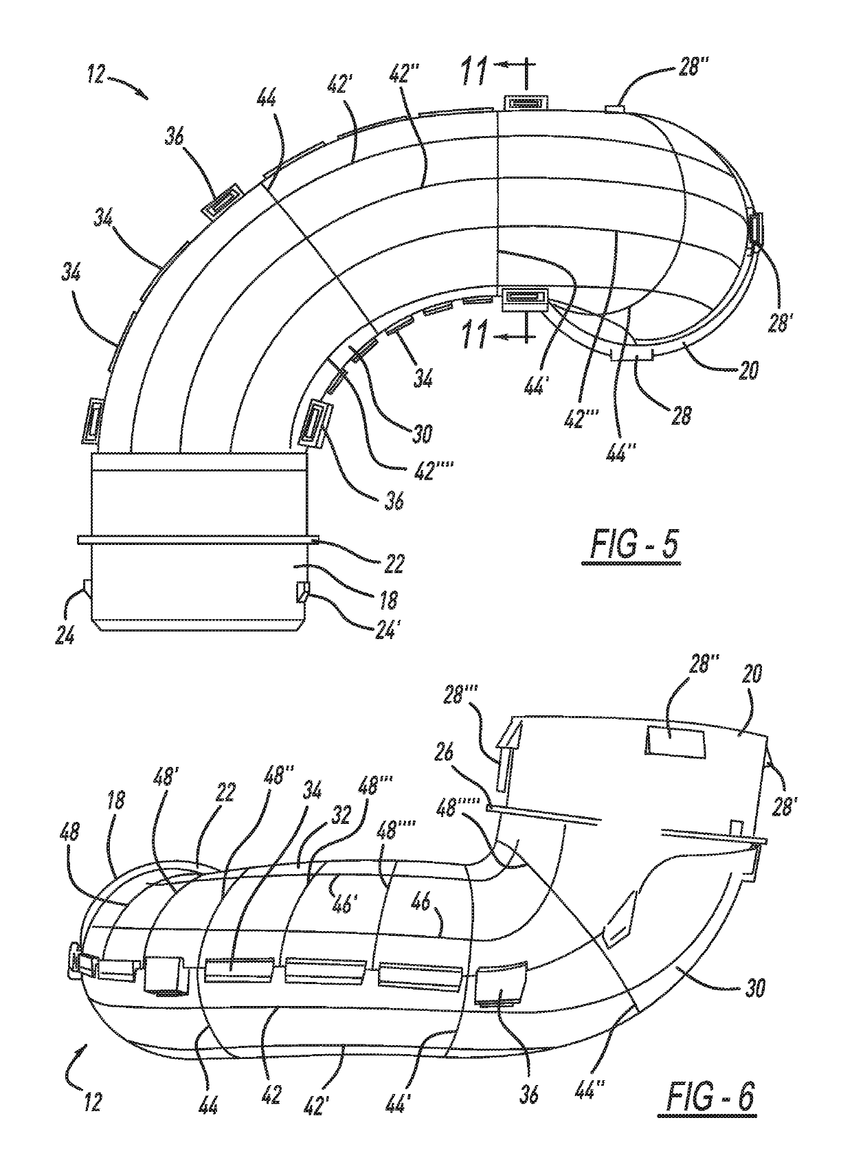
The disclosed invention is a crushable or collapsible air induction duct that has strategically positioned and patterned crack-initiating grooves that allow it to be crushed in an impact event, protecting adjacent and higher cost under hood components from damage. The crushable air duct is made of a readily breakable, rigid polymerized material such as polypropylene, high-density polyethylene, or acrylonitrile styrene acrylate. The invention has been tested in impact events and has been shown to perform at least as well as known elastomer versions, with a preferred crushable force of 500N.

Problems solved by technology

This problem can arise even in a low speed impact in which components of the “cooling pack” (the A / C condenser, the radiator, the fan unit, and the fan shroud) as well as the bolster are pushed vehicle-rearward by about 100 mm.
Given the concern over a possible impact event, today's AIS dirty side duct (DSD) is at risk of not meeting the safety LSD cascaded target.
However, elastomeric parts can cost and weigh more than that of molded rigid plastic parts.
Such components also tend to be heavier than molded rigid plastic parts and thus add undesirable extra weight to the vehicle.
Accordingly, known approaches to reducing damage to expensive under hood components in an impact event have not always produced satisfactory results.

Method used


Image

  • Breakable duct for use with a motor vehicle air induction system
  • Breakable duct for use with a motor vehicle air induction system
  • Breakable duct for use with a motor vehicle air induction system

Examples


Embodiment Construction

[0025]In the following figures, the same reference numerals will be used to refer to the same components. In the following description, various operating parameters and components are described for different constructed embodiments. These specific parameters and components are included as examples and are not meant to be limiting.

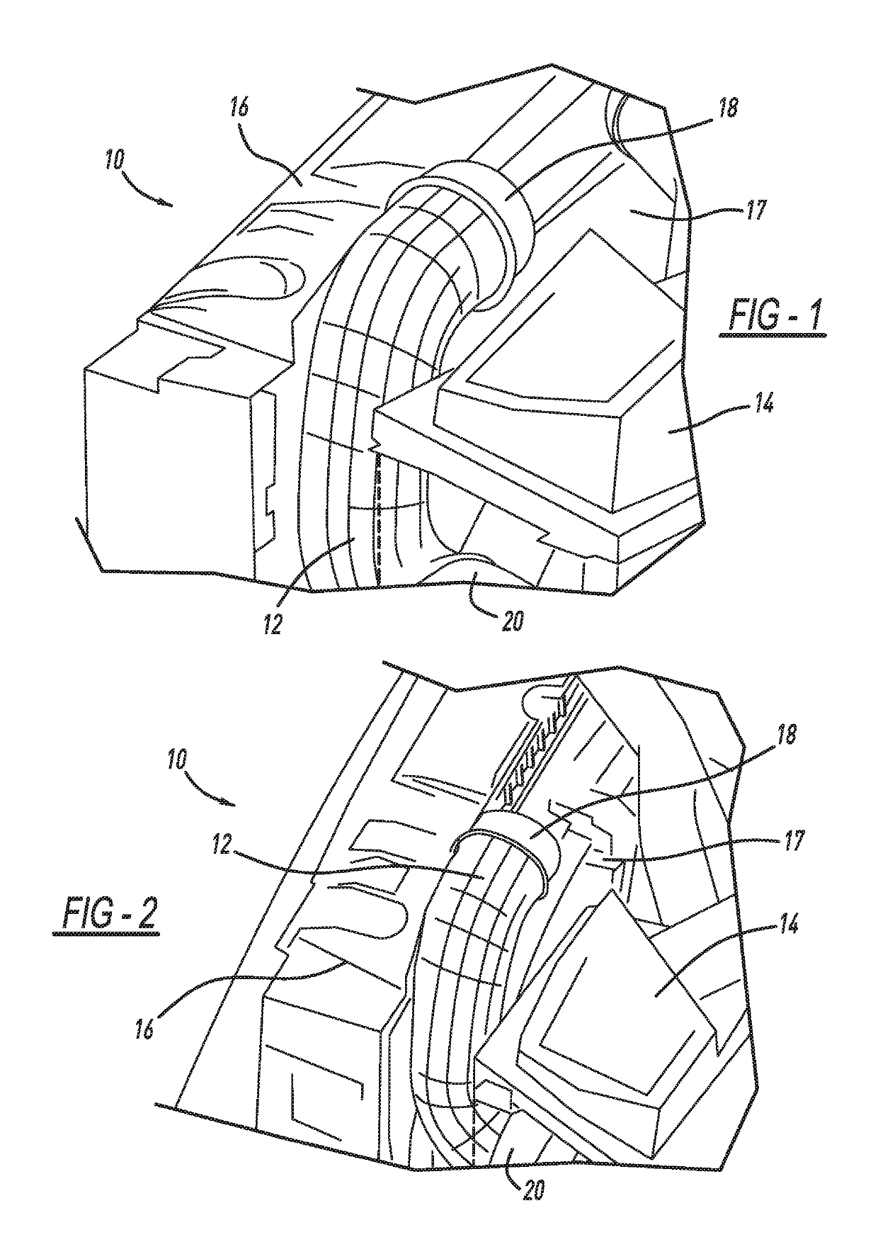
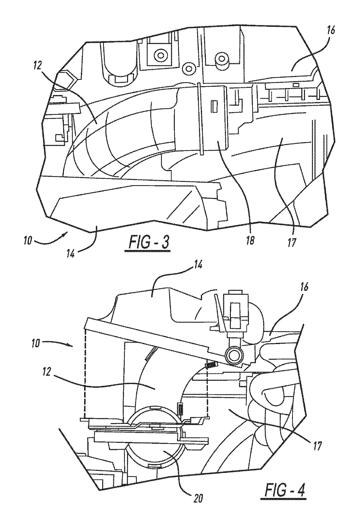
[0026]The accompanying figures and the associated description illustrate an intake manifold according to the disclosed inventive concept. Particularly, FIGS. 1 through 4 illustrate the crushable duct of the air induction system illustrated in position in an engine compartment of a vehicle under normal operating conditions. The crushable duct itself is illustrated in isolation in various views in FIGS. 5 through 11. The crushable duct is illustrated in its crushed condition within an engine compartment following an impact event in FIG. 12.

[0027]It is to be understood that the under-hood features and arrangement may be different from those illustrated in FIGS...


PUM

PropertyMeasurementUnit
forceaaaaaaaaaa
lengthaaaaaaaaaa
densityaaaaaaaaaa

Abstract

The disclosed inventive concept provides a crushable air duct having formed thereon a series of strategically positioned and patterned crack-initiating grooves. The grooves allow the air duct to be crushed in an impact event and a specified impact force, thereby protecting adjacent and higher cost under hood components from damage. In an impact event, the series of grooves allows the cracks in the air duct to readily propagate throughout the pattern in a controlled and predictable manner. The crushable air duct is formed from a rigid polymerized material. The duct includes an inlet and an outlet. The grooves are formed on either or both the exterior surface and the interior surface of the duct. Some of the grooves extend generally between the inlet and the outlet. These grooves are preferably parallel. Other grooves are circumferentially formed around the duct. At least some of the parallel and circumferential grooves intersect.

Description

TECHNICAL FIELD[0001]The disclosed inventive concept relates generally to air induction systems for use with the internal combustion engine of a vehicle. More particularly, the disclosed inventive concept relates to a crushable or collapsible air conduit or duct having strategically positioned and patterned break-initiating grooves that provide a wall thickness engineered to fail at a specified load to prevent subsequent damage to higher cost under-hood components.BACKGROUND OF THE INVENTION[0002]The internal combustion engine conventionally includes an air induction system (AIS) for delivering ambient air to the throttle body and ultimately into the combustion chamber as part of an air-fuel mixture. The air induction system includes an air duct that initially takes in the ambient air and passes the incoming air into and through the air filter box. Typically the air duct is a generally inexpensive unit that is conventionally positioned adjacent more expensive under hood components s...

Claims


Application Information

Patent Timeline
Patent Type & Authority Patents(United States)
IPC IPC(8): F02M35/10F16F7/00
CPCF16F7/003F02M35/10091F02M35/10236B60K13/02F02M35/10321F02M35/104
Inventor ROLLINS, SCOTT M.LIU, JOHN QINGRUIMARSH, JOHNWELLS, ERIC
Owner FORD GLOBAL TECH LLC
Learn More