Antenna segment and multi-segment antenna

a multi-segment, antenna technology, applied in the direction of antennas, antenna details, antennas, etc., can solve the problems of high labor intensity, high cost, and high cost of core insertion, and achieve the effect of sufficient or good antenna efficiency and cost-effectiveness

Active Publication Date: 2021-08-10
EPCOS AG
View PDF13 Cites 0 Cited by
  • Summary
  • Abstract
  • Description
  • Claims
  • Application Information

AI Technical Summary

Benefits of technology

[0005]Embodiments provide an antenna segment and a multi-segment antenna as well as methods for producing the antenna segment and the multi-segment antenna, allowing for a cost-effective provision of antenna segments and multi-segment antennas with sufficient or good antenna efficiency.
[0007]By using such antenna segments, manufacturing and labor costs can be reduced in comparison with the manufacturing of long antennas, in particular long low frequency antennas. Using a highly sophisticated manufacturing process and equipment, e.g. winding machines with synchronized driver and support, is not necessary. In the case of a monolith ferrite core, where the coil is wound directly on the core, due to a size proportion and its natural fragility the ferrite core is easily breakable as a result of handling and / or coil winding tension. Additionally, winding directly on the ferrite core demands usage of highly sophisticated winding machines to avoid torsion of the ferrite core. For multi-core segments and single-coil solutions the core insertion, in particular the ferrite core insertion, to the coil is a highly labor-intensive process affected by the risk of coil damage. Additionally, the long slide of ferrite core segments demands sophisticated production fixtures or jigs.
[0008]Furthermore, the antenna segments can reliably be connected together to form a long antenna. Thus, the connected antenna elements serve as a long antenna and not as separate antennas. Thus, sufficient or good antenna efficiency can be reached.
[0009]In one embodiment according to the first aspect, the first end section comprises a first shape and the second end section comprises a second shape complementary to the first shape. Advantageously, the shapes of the first and second end sections allow for optimal coupling of the coil carrier and wire coil segments, as well as for easy manufacturing.
[0014]In one embodiment according to the second aspect, an adhesive substance is arranged between respective joining magnetic cores of the antenna segments. Advantageously, in this way gaps between the magnetic cores can be avoided or smallest possible gaps between the magnetic cores can be ensured.

Problems solved by technology

For multi-core segments and single-coil solutions the core insertion, in particular the ferrite core insertion, to the coil is a highly labor-intensive process affected by the risk of coil damage.
Additionally, the long slide of ferrite core segments demands sophisticated production fixtures or jigs.

Method used


Image

  • Antenna segment and multi-segment antenna
  • Antenna segment and multi-segment antenna
  • Antenna segment and multi-segment antenna

Examples


Embodiment Construction

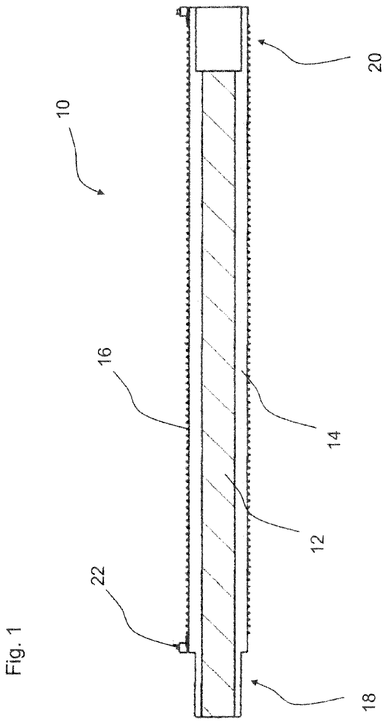
[0024]FIG. 1 shows an exemplary embodiment of an antenna segment 10 in a longitudinal section view.

[0025]The antenna segment 10 comprises a coil carrier 14 with a first end section 18 and a second end section 20. Furthermore the antenna segment 10 comprises a wire coil 16 which is arranged around the coil carrier 14 and a magnetic core 12 arranged in the coil carrier 14. The magnetic core 12 and the wire coil 16 are arranged such that in the first end section 18 of the coil carrier 14 the magnetic core 12 and the coil carrier 14 extend beyond the wire coil 16 and in the second end section 20 of the coil carrier 14 the coil carrier 14 and the wire coil 16 extend beyond the magnetic core 12.

[0026]Thus, the wire coil 16 is shifted and arranged asymmetrically with respect to the magnetic core 12. The coil carrier 14 is carrying the wire coil 16 even beyond the core's end, so that the wire coil 16 extends beyond the core's end.

[0027]Thus, the first end section 18 is not covered by the wi...


PUM


Abstract

An antenna segment and a multi segment antenna are disclosed. In an embodiment an antenna segment includes a coil carrier comprising a first end section and a second end section, a wire coil arranged around the coil carrier and a magnetic core arranged in the coil carrier, wherein the magnetic core and the wire coil are arranged such that in the first end section the magnetic core and the coil carrier extend beyond the wire coil and in the second end section the coil carrier and the wire coil extend beyond the magnetic core.

Description

[0001]This patent application is a national phase filing under section 371 of PCT / EP2017 / 080516, filed Nov. 27, 2017, which claims the priority of German patent application 102016125211.5, filed Dec. 21, 2016, each of which is incorporated herein by reference in its entirety.TECHNICAL FIELD[0002]The invention relates to an antenna segment for an antenna with a magnetic core and a multi-segment antenna. Additionally the invention relates to methods for producing an antenna segment and a multi-segment antenna.BACKGROUND[0003]In current technology, especially in the automotive engineering sector, there is an increasing demand for inductive assembly components and, especially, ferrite antennas, wherein the ferrite antennas, due to installation reasons, should be as long and narrow as possible. Such ferrite antennas are used especially in connection with key-less actuation and / or closure devices for vehicles, the ferrite antennas being disposed in door grips, in an interior, or in a bump...

Claims


Application Information

Patent Timeline
Patent Type & Authority Patents(United States)
IPC IPC(8): H01Q7/06H01Q1/32
CPCH01Q7/06H01Q1/3241H01F27/263H01Q7/08
Inventor SZCZOTKA, RAFAL
Owner EPCOS AG
Why Eureka
Try Eureka