Measuring instrument that detects displacement of a contact point

a contact point and measurement instrument technology, applied in the field of measuring instruments, can solve the problems of difficult to precisely set the preset value to a target value, troublesome and cumbersome, etc., and achieve the effect of quick and simple operation of setting operations

Active Publication Date: 2020-03-24
MITUTOYO CORP
View PDF4 Cites 0 Cited by
  • Summary
  • Abstract
  • Description
  • Claims
  • Application Information

AI Technical Summary

Benefits of technology

[0008]An object of the present invention is to provide a measuring instrument in which setting operations can be quickly and simply performed.

Problems solved by technology

It is very troublesome and cumbersome to set a numerical value (numeralize) by pressing a plurality of operation buttons or key switches many times. In addition, if the value detected by the encoder is intactly used as a preset value, it is difficult to precisely set the preset value to a target value.

Method used


Image

  • Measuring instrument that detects displacement of a contact point
  • Measuring instrument that detects displacement of a contact point
  • Measuring instrument that detects displacement of a contact point

Examples


first embodiment

[0023]The first embodiment of the present invention will be described.

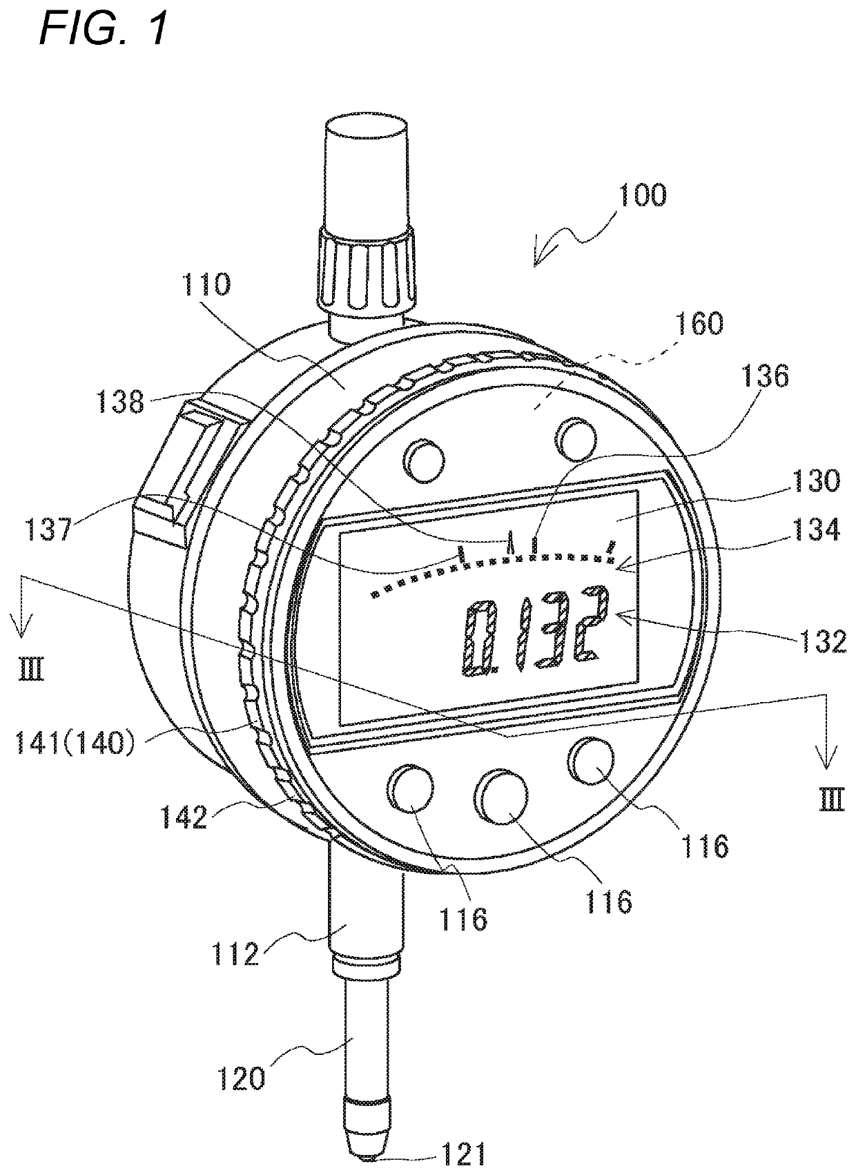
[0024]FIG. 1 is a perspective view showing the exterior of a digital display type dial gauge 100.

[0025]The dial gauge 100 is configured to digitally display a displacement of a spindle 120 on a display unit 130.

[0026]The dial gauge 100 includes a case 110, the spindle 120, the display unit 130, input means (116, 140) and a control circuit unit 160.

[0027]The case 110 is a short cylinder-shaped case body.

[0028]A stem 112 is provided to protrude from a side surface of the case 110, and the stem 112 serves as a bearing for the spindle 120.

[0029]The spindle 120 has a contact point 121 at a distal end thereof and is supported to be movable axially back and forth through the case 110. An encoder for detecting a displacement of the spindle 120 is built in the case 110.

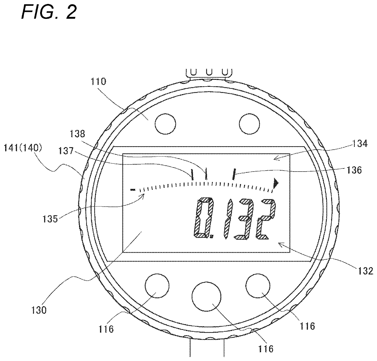
[0030]The display unit 130 is arranged substantially on the central region of a front-side end surface of the case 110. The display unit 130 is, for example...

example 1

of Tolerance Setting

[0073]For example, if a masterwork already exists and a tolerance of a product is + / −0.3 mm with respect to the masterwork, the tolerance of + / −0.3 mm is preferably set in the dial gauge 100. Since the dial gauge 100 is a digital type, it is easy to cause a user to be notified by color or sound when a measured value of an object to be measured is deviated from the set tolerance.

[0074]The user inputs a numerical value of “0.3” into the dial gauge 100 while selecting the tolerance setting mode by pressing a switch.

[0075]The numerical value of “0.3” is a small numerical value.

[0076]At this time, the user slowly rotates the rotary ring 141. Then, h(V) becomes a small value and thus the conversion value N also becomes a small vale.

[0077]In this way, it is possible to simply input a small numerical value, such as “0.3”, by only a very natural operation of slowly rotating the rotary ring 141. The numerical value (e.g., 0.3) inputted as described above is indicated on th...

example 2

of Tolerance Setting

[0078]For example, if a masterwork does not exist but an allowable range of a product is instructed as 49.7 mm to 50.3 mm by an instruction on the design drawing, a tolerance of 49.7 mm to 50.3 mm is set in the dial gauge 100.

[0079]The numerical value “49.7” or “50.3” is a larger value than “0.3”.

[0080]At this time, like the above case, a user only has to rotate the rotary ring 141, but quickly rotates the rotary ring 141 since such larger numerical values have to be inputted. Then, h(V) becomes a large value and thus the conversion value N also becomes a large value. In this way, it is possible to simply input large numerical values, such as “49.7” or “50.3”, by only a very natural operation of quickly rotating the rotary ring 141.

[0081]If the numerical value of the indication is increased with the same step as when “0.3” is inputted, a significant operation is required to cause the numerical value to reach just “49.7”.

[0082]In the case of convention machines in...


PUM


Abstract

A measuring instrument is configured to detect a displacement of a contact point provided to be movable and to digitally display a measured value on a display unit provided on an outer surface of a case. The measuring instrument includes an input unit. The input unit is provided on the outer surface of the case and is configured to allow a user to input to the input unit through a manual operation. The input unit includes a sensor which is configured to detect an amount of operation and a speed of operation. The amount of operation is converted into a conversion value in view of the speed of operation and then is displayed on the display unit.

Description

CROSS-REFERENCE TO RELATED APPLICATION[0001]This application claims the benefit of Japanese Patent Application No. 2016-151192, filed on Aug. 1, 2016, the entire contents of which are hereby incorporated by reference, the same as if set forth at length, the entire of which are incorporated herein by reference.TECHNICAL FIELD[0002]The present invention relates to a measuring instrument. In particular, the present invention relates to a small measuring instrument configured to digitally display a measured value on a display unit, such as a digital dial gauge (digital indicator), a digital micrometer, a digital vernier calipers and the like.BACKGROUND ART[0003]As small measuring instruments which allow a measurer to carry out measurement by hand, for example, a dial gauge, a vernier calipers or a micrometer are known.[0004]As advance preparations before a work is actually measured, a variety of setting need to be performed on a measuring instrument.[0005]For example, operations, such a...

Claims


Application Information

Patent Timeline
Patent Type & Authority Patents(United States)
IPC IPC(8): G01B3/22G01D13/22G01B9/00G06F3/042G01B3/18G01B3/24G06F7/498
CPCG01B9/00G01B3/22G06F3/042G01D13/22G06F7/4983G01B3/18G01B3/24G01B3/20
Inventor NIWANO, ATSUYA
Owner MITUTOYO CORP
Why Eureka
Try Eureka