
Cursor control for aircraft display device

a display device and cursor control technology, applied in the field of aircraft systems, can solve the problems of large pilot workload, use of primary cursor control devices, and the need for a large number of key actuations,

Active Publication Date: 2020-03-24
BOMBARDIER INC
View PDF35 Cites 0 Cited by
  • Summary
  • Abstract
  • Description
  • Claims
  • Application Information

AI Technical Summary

Benefits of technology

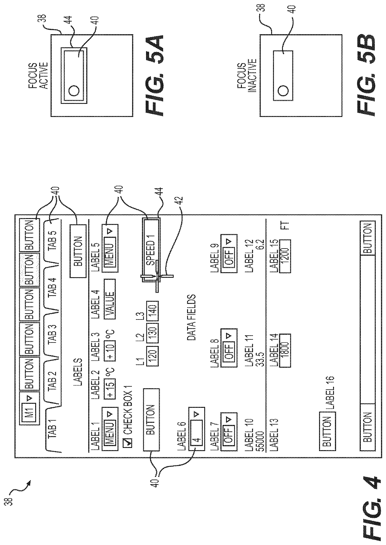
[0019]The machine-readable instructions may be configured to cause the data processor to, conditioned upon a widget inside the current cell having an active focus, determine the next position of the cursor to be in a next cell adjacent the current cell. The next position of the cursor may correspond to a destination point in the next cell. The destination point in the next cell may be positioned to prevent at least some obstruction of information displayed in the next cell by the cursor.
[0036]The method may comprise: conditioned upon a widget inside the current cell having an active focus, determining the next position of the cursor to be in a next cell adjacent the current cell. The next position of the cursor may correspond to a destination point in the next cell. The destination point in the next cell may be positioned to prevent at least some obstruction of information displayed in the next cell by the cursor.
[0051]The next position of the cursor may correspond to a destination point in the next cell. The destination point in the next cell may be positioned to prevent at least some obstruction of information displayed in the next cell by the cursor.

Problems solved by technology

The directional movement keys may be used when the use of the primary cursor control device may not be practical such as during episodes of turbulence.
Existing methods of controlling the movement of a cursor using directional movement keys can require significant pilot workload due to the concentration and attention required to position the cursor adequately.
This can results in a large number of key actuations being required if the fixed distance is small and the target position is far from the initial position of the cursor.
Alternatively, if the fixed distance is large and the target is close to the initial position of the cursor, there may be a risk of jumping over the target position.
Slewing can take a relatively long time to move a cursor to the desired target when the target position is far and can also require sustained attention of the pilot to achieve adequate positioning of the cursor.

Method used


Image

  • Cursor control for aircraft display device
  • Cursor control for aircraft display device
  • Cursor control for aircraft display device

Examples


Embodiment Construction

[0078]Aspects of various embodiments are described through reference to the drawings.

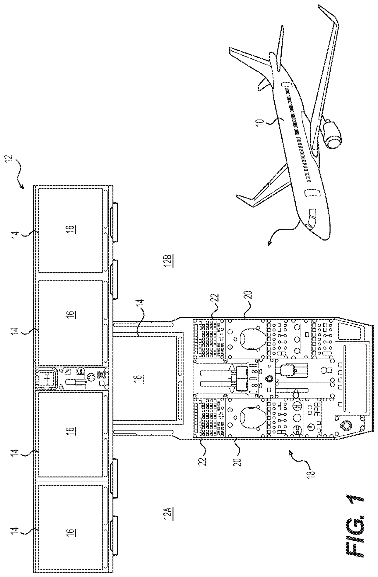
[0079]The present disclosure describes devices, systems, methods and computer program products useful in controlling the movement of a cursor on a display device. While the present disclosure is mainly directed to display devices of aircraft flight decks, the devices, systems, methods and computer program products described herein could also be used in other applications requiring control of a movable cursor over a display area. For example, the devices, systems, methods and computer program products could be used for controlling cursor movement on displays in other portions of aircraft, of other types of mobile platforms (e.g., vehicles) and also in stationary applications. The devices, systems, methods and computer program products disclosed herein could also be used for, but not limited to, controlling cursor movement on displays associated with aircraft electronic flight bags, aircraft cabin man...


PUM


Abstract

Systems, methods and computer program products for controlling the movement of a cursor on a display device in an aircraft are disclosed. An exemplary method disclosed comprises the use of a digital representation of a grid defining a plurality of cells overlaying at least a portion of a display area of the display device to control the movement of the cursor over the display area. The grid may be invisible to the user during operation.

Description

CROSS-REFERENCE TO RELATED APPLICATION[0001]This application is a national phase application under 35 U.S.C. 371 of International Patent Application No. PCT / IB2015 / 052249 filed on Mar. 26, 2015, which claims priority from U.S. Provisional Patent Application Ser. No. 61 / 972,501, filed on Mar. 31, 2014, the entire content of which is incorporated herein by reference.TECHNICAL FIELD[0002]The disclosure relates generally to interaction with aircraft systems and more particularly to the control of a movable cursor on a display device in an aircraft.BACKGROUND OF THE ART[0003]The use of movable cursors on display devices of aircraft flight decks is known. To provide redundancy, some aircraft provide a primary cursor control device such as a trackball and alternate means of controlling the cursor such as directional movement keys on a keyboard. The directional movement keys may be used when the use of the primary cursor control device may not be practical such as during episodes of turbule...

Claims


Application Information

Patent Timeline
Patent Type & Authority Patents(United States)
IPC IPC(8): G06F3/0481G06F3/0489G06F3/0484
CPCG06F3/04842G06F3/04812G06F3/04892B64D43/00
Inventor OUELLETTE, BENOITLEBLANC, FREDERICDOYON POULIN, PHILIPPESEGUIN TREMBLAY, NOEMIE
Owner BOMBARDIER INC
Learn More