Self-compensating drip irrigation emitter
a drip irrigation and emitter technology, applied in spray nozzles, climate change adaptation, horticulture, etc., can solve the problem of small size, achieve the effect of preventing total obstruction, simple and inexpensive arrangements, and constant water drip
- Summary
- Abstract
- Description
- Claims
- Application Information
AI Technical Summary
Benefits of technology
Problems solved by technology
Method used
Image
Examples
first embodiment
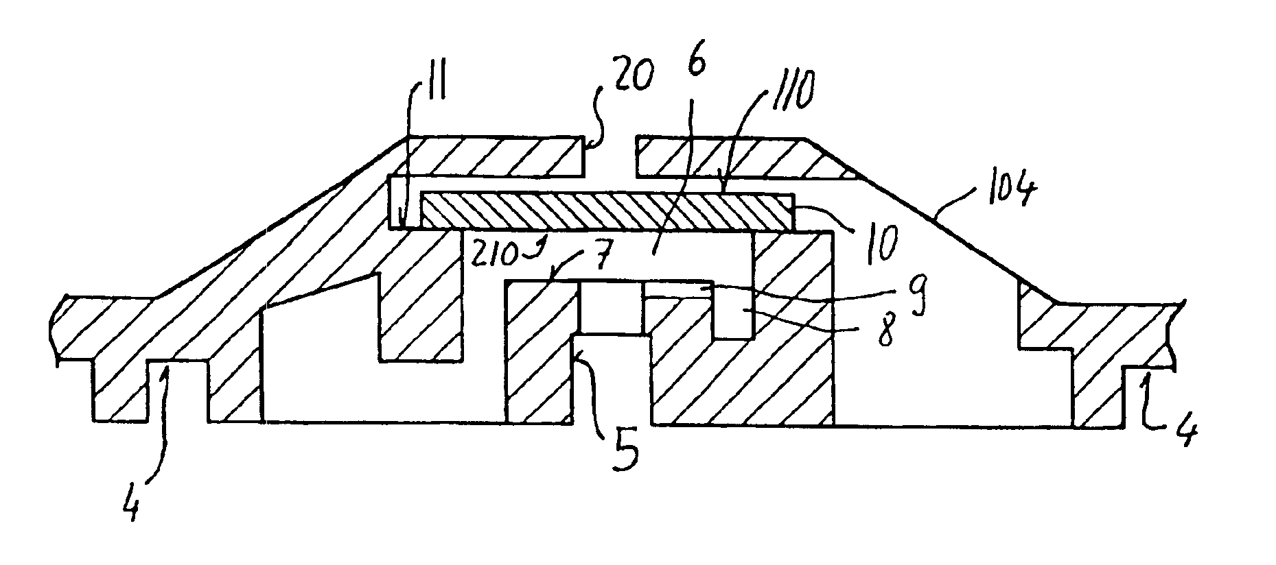
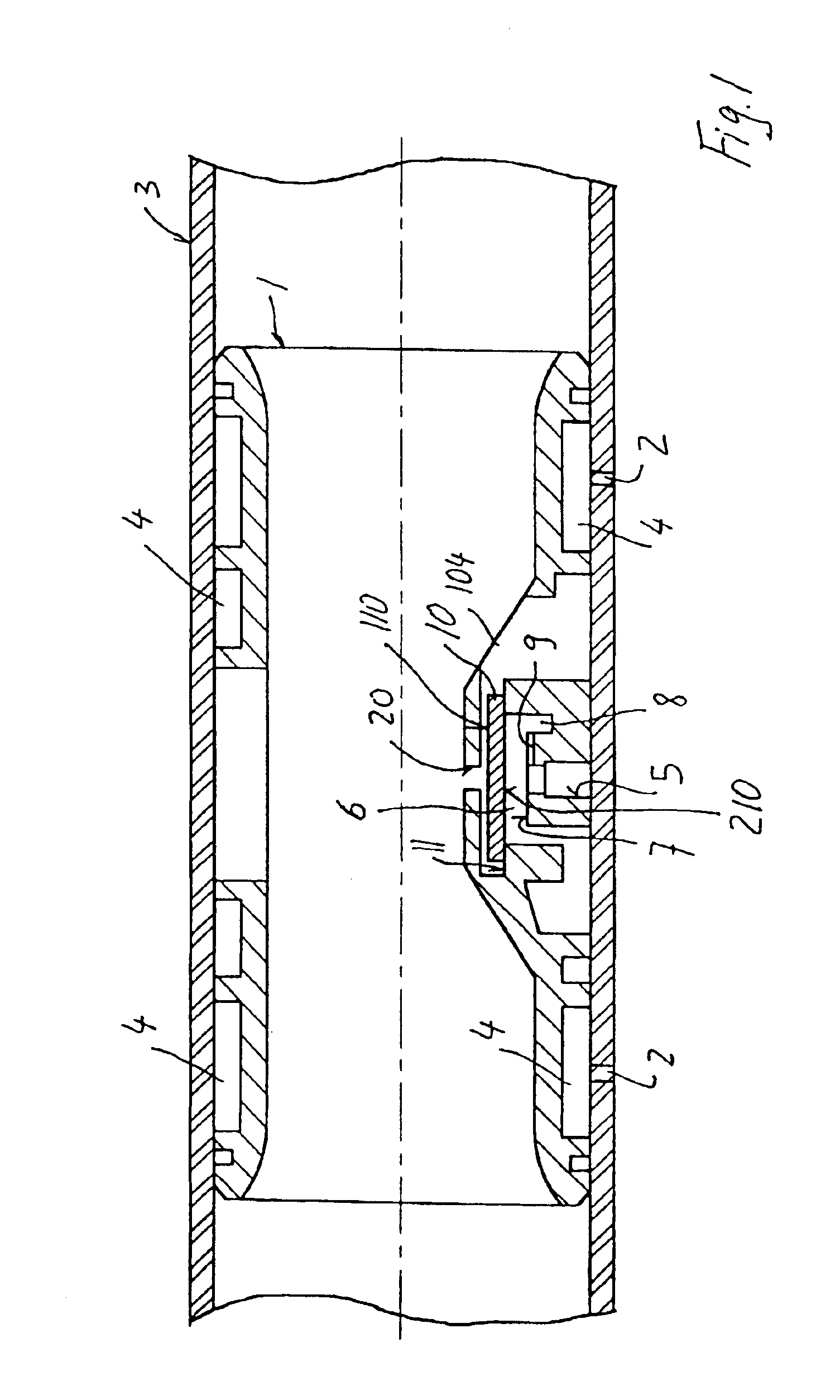
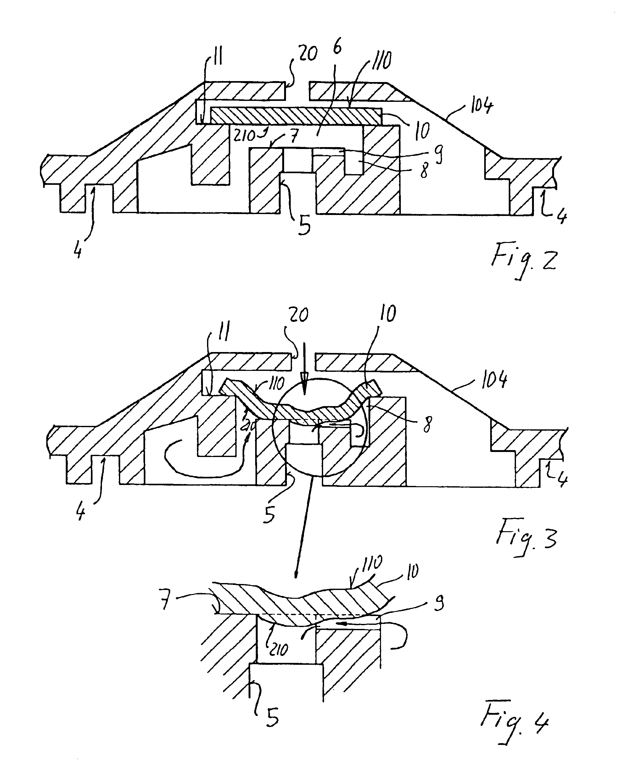
[0060]A first arrangement is shown in FIGS. 5 to 7, relating to the invention. In this case, in the ending section opening into the water discharge orifice 5, the groove 9 branches into two separate end grooves 12, both opening out at the edge of said orifice 5. A wall member 13 is interposed between the two branch grooves 12 which has a streamlined shape directed toward the main groove 9, and such as to allow water to flow toward the central orifice 5. This wall member 13 extends radially to a certain extent beyond the peripheral edge of the orifice 5 toward the center thereof and, still to a certain extent, in the axial direction of said orifice 5.
[0061]The wall member 13 has a top flat surface 113, which extends level with the flat surface 7 and, in very high pressure conditions, acts as a membrane rest member, at the critical area whereat the two branch grooves 12 open into the orifice 5, thereby preventing occlusion thereof. The principle is better explained in FIGS. 25 to 27. ...
third embodiment
[0064]Referring now to FIGS. 11 to 13, the emitter according to the invention is shown, in which the main groove 9 has two branches 15 which extend along an arc of a circle and in opposite directions with respect to its longitudinal axis, and open into the central orifice 5 at two diametrically opposite areas, disposed along an axis perpendicular to the longitudinal axis of the main groove 9. In this case, the main groove 9 and the two branches 15 have the same depth and the same width. When fluid pressure is very high, and the membrane 10 is strongly deformed, a flow rate reduction may be expected as described for prior art. Nevertheless, three outlets into the central orifice are provided, not one like in prior art, so that the minimum flow may be maintained to a substantially constant value. Obviously, the branches 15 may be provided in a greater number and / or with an at least partly different profile from the one described above.
fourth embodiment
[0065]FIGS. 14 to 16 show the inventive emitter wherein an extension 116 of the flat surface 7 toward the interior of the central orifice 5 is provided on one of the two side portions directly adjacent to the edge of the groove 9, which extension consists of a rib 16 which also extends at least partly in the axial direction of said orifice 5. Although the groove 9 essentially has the same characteristics as the groove 9 described in prior art, the upper surface 116 of the rib element 16 advantageously forms an additional support and bearing member for the membrane 10 in the outlet portion of the groove 9 at the edge of the orifice 5, thereby preventing the groove 9 from being obstructed and allowing a constant minimum flow.
PUM
 Abstract
Description
Claims
Application Information
 - R&D
- Intellectual Property
- Life Sciences
- Materials
- Tech Scout
- Unparalleled Data Quality
- Higher Quality Content
- 60% Fewer Hallucinations
Browse by: Latest US Patents, China's latest patents, Technical Efficacy Thesaurus, Application Domain, Technology Topic, Popular Technical Reports.
© 2025 PatSnap. All rights reserved.Legal|Privacy policy|Modern Slavery Act Transparency Statement|Sitemap|About US| Contact US: help@patsnap.com


