Arrangement for inhibiting range shifting in a transmission
Active Publication Date: 2011-07-21
VOLVO LASTVAGNAR AB
29 Cites 0 Cited by
AI-Extracted Technical Summary
Problems solved by technology
The springs, therefore, do not facilitate bringing the synchronizing cones up to the same speeds before engagement of the teeth on the shift collar and the input shaft or the gear reduction arrangement.
As a consequence, the gears can clash during a range shift in reverse, damaging the “coast sides” of the teeth, i.e., the sides of the teeth that are not in contact during rotation corresponding to a forward direction and that are in cont...
Method used
To inhibit range shifting, a range shift inhibitor valve 129 for opening and closing flow communication between the switch valve 111 and the low range shift valve chamber 125 can be provided. The range shift inhibitor valve 129 can be adapted to effectively disable the range shift valve 109. The controller 107 opens and closes the range shift inhibitor valve 129 in response to the inhibit range shift signal from what shall herein be referred to generally as a sensor indicating that one or both of the main shaft and the output shaft are rotating in a reverse dire...
Benefits of technology
The present invention relates to a transmission and, more particularly, to a multi-gear, multi-range t...
Abstract
An arrangement for inhibiting axial movement of a range clutch in a transmission includes a driver adapted to move the range clutch axially on an output shaft between a high range position and a low range position, a sensor arrangement adapted to sense at least one of reverse rotational direction and potential reverse rotational direction of at least one of a main shaft and the output shaft and to generate an inhibit range shift signal upon sensing at least one of reverse rotational direction and potential reverse rotational direction, and a controller adapted to inhibit operation of the driver upon receipt of the inhibit range shift signal from the sensor arrangement. A transmission and a vehicle including such an arrangement are also disclosed. A method for inhibiting axial movement of a range clutch in a transmission, and a method of retrofitting a transmission with an arrangement for inhibiting axial movement of a range clutch are also disclosed.
Application Domain
Fluid actuated clutchesToothed gearings +3
Technology Topic
ClutchVariator +2
Image
Examples
- Experimental program(1)
Example
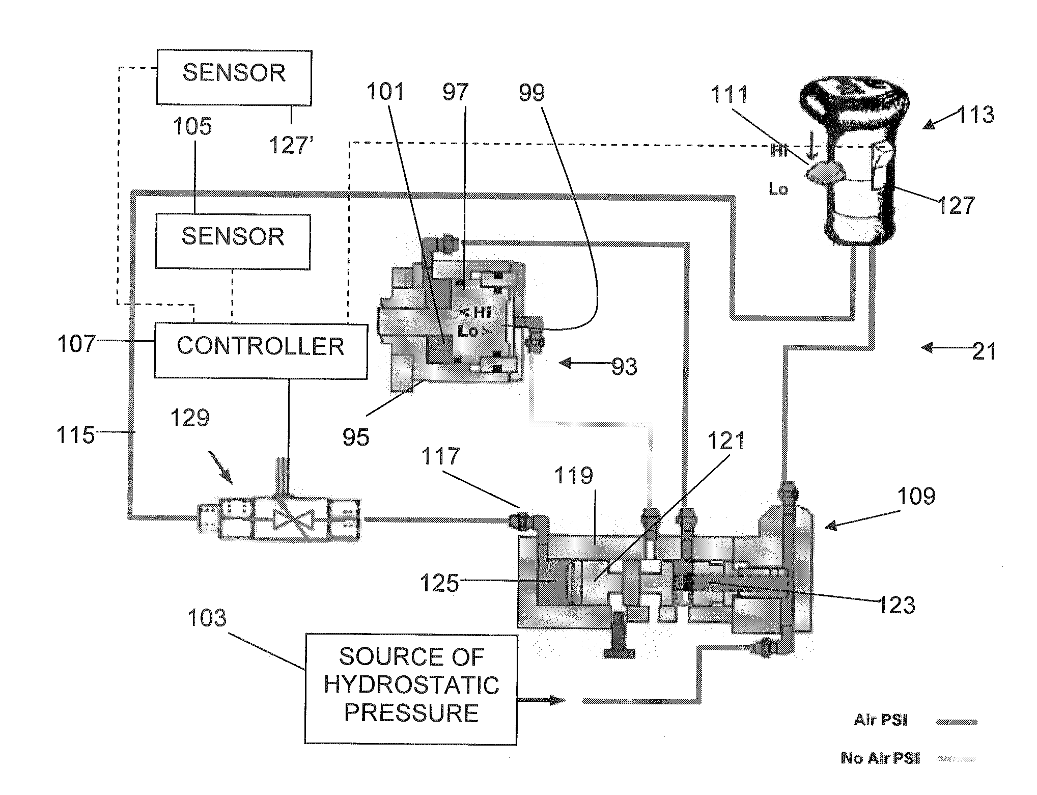
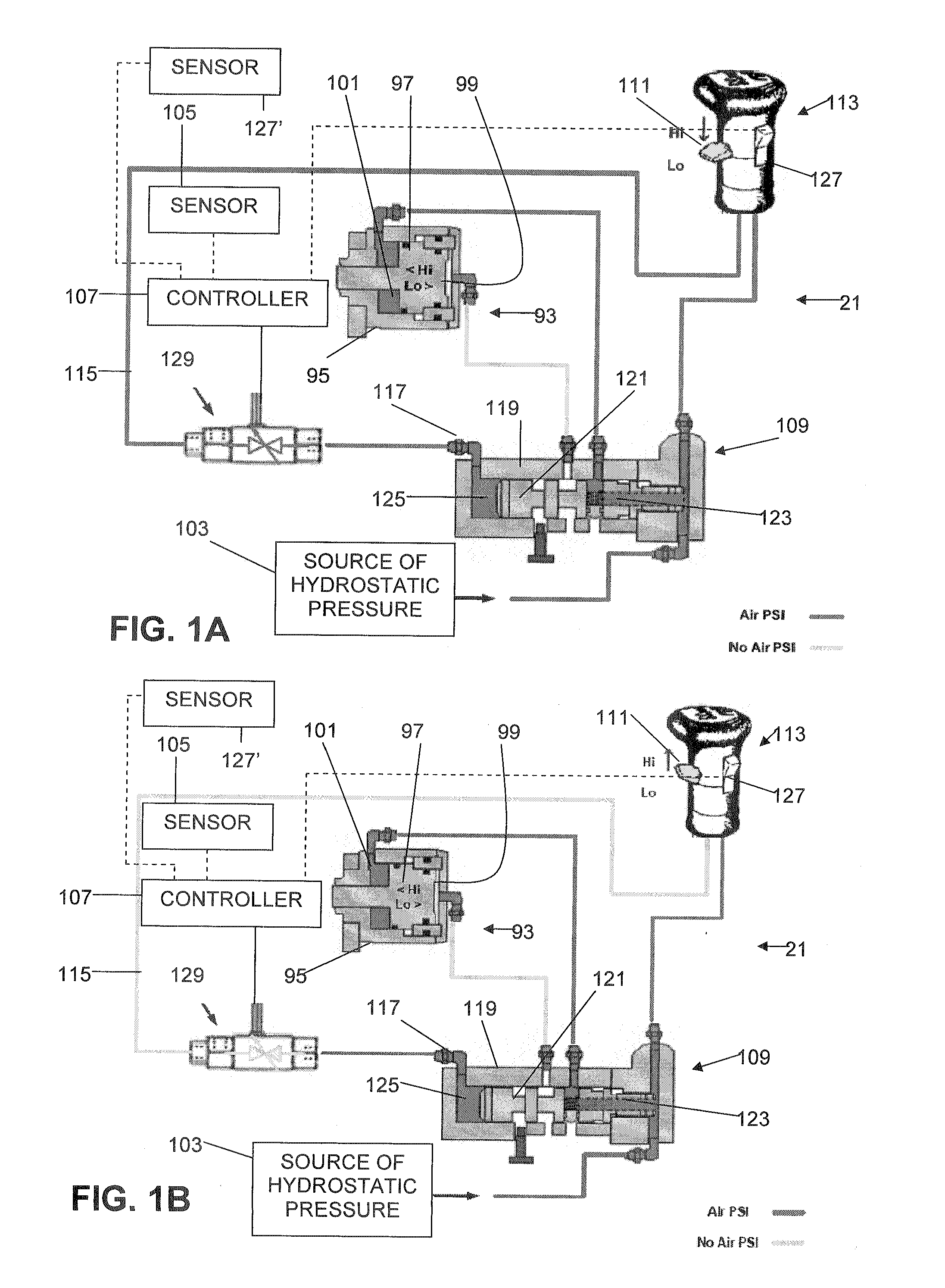
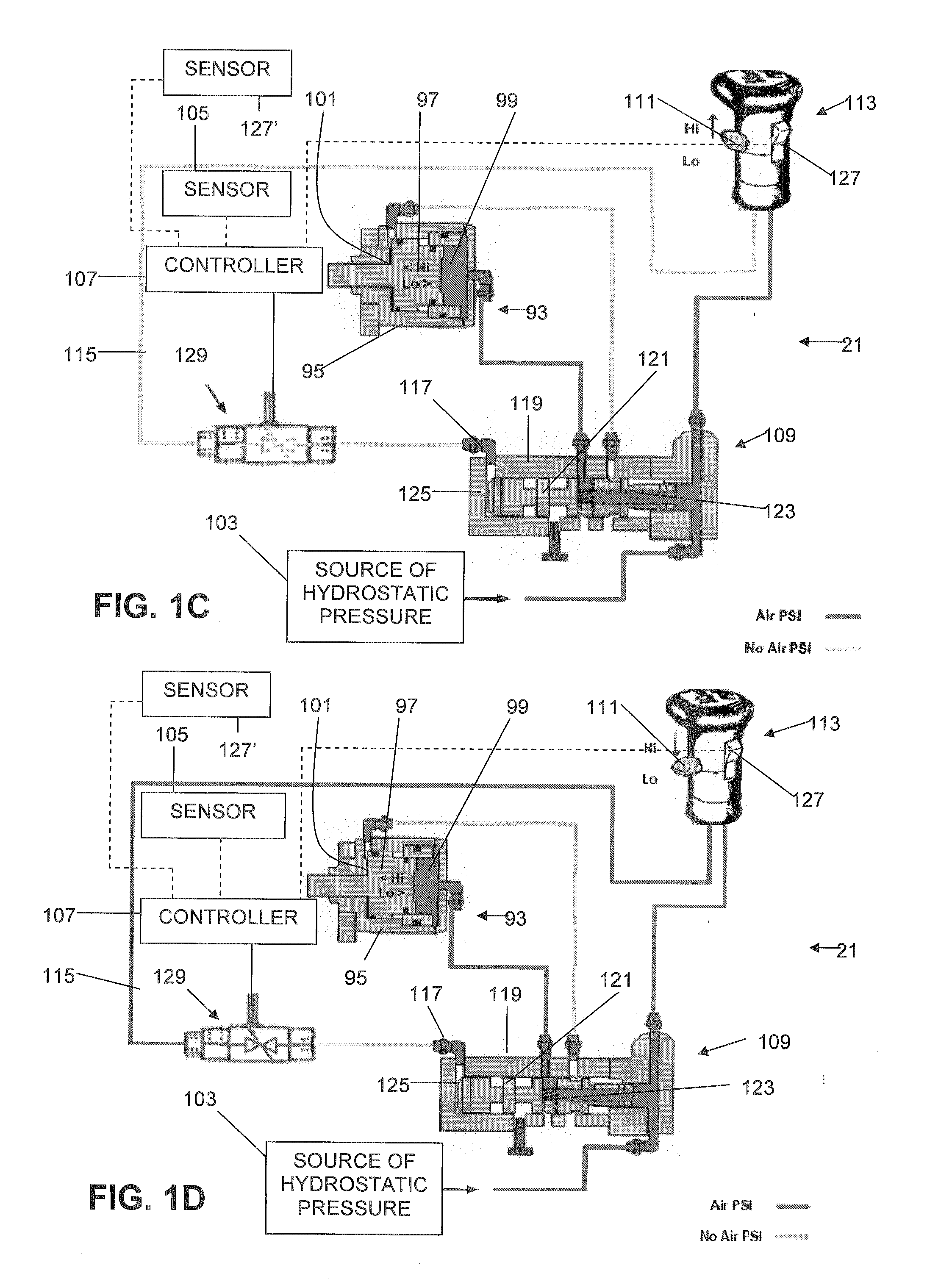
FIGS. 1A-1D show an arrangement 21 for inhibiting axial movement of a range clutch 87 in a transmission 25 of the general type shown in FIGS. 2A-2C. The illustrative transmission 25 comprises a main shaft 27 and an output shaft 29. The range clutch 87, shown in a neutral position in FIG. 2A, is movable on the output shaft 29 between a high range position (FIG. 2B) and a low range position (FIG. 2C) to modify a main shaft 27 rotational speed to at least one different output shaft 29 rotational speed. It will be appreciated that the transmission 25 can form part of a vehicle such as a heavy truck.
The transmission 25 comprises a main portion 25a and an auxiliary portion 25b. The main portion 25a comprises a plurality of selectable gears comprising a forward gear, which may comprise a plurality of forward gears 31, 33, 35, 37, and 39, and a reverse gear 41, which may comprise a plurality of reverse gears (only one reverse gear shown), for providing different speed ratios between an input shaft 43 and the main shaft 27. Clutches 45, 47, 49, 51, and 53 are splined to the main shaft 27 and axially movable by an operator to selectively couple one of the gears 31, 33, 35, 37, 39, and 41 to the main shaft 27 via gears 55, 57, 59, 61, 63, and 65 fixed on a countershaft 67 that is always driven by the input shaft via gears 31 and 55. An idler gear 69 is provided to mesh with the reverse gear 41 and the gear 65 when the transmission 25 is shifted into reverse. A main output gear 73 is axially and rotationally fixed at an end of the main shaft 27. A high range synchronizing clutch portion 75 is also connected to the end of the main shaft 27.
The auxiliary portion 25b of the transmission 25 comprises a large gear 77 and a small gear 79 mounted on an auxiliary countershaft 81. The large gear 77 meshes with the main output gear 73 and the small gear 79 meshes with an auxiliary output gear 83 that is axially fixed relative to the output shaft 29 and is not splined to the output shaft. A low range synchronizing clutch portion 85 is connected to the auxiliary output gear 83. A range clutch 87 is splined to the output shaft 29 and comprises a high range synchronizer cone 89 and a low range synchronizer cone 91 for engaging with the high range synchronizing clutch portion 75 (FIG. 2B) and the low range synchronizing clutch portion 85 (FIG. 2C), respectively, when the range clutch is moved left or right from the position shown in FIG. 2A. U.S. Pat. No. 6,571,927 discloses a range clutch with a synchronizing arrangement of a general type particularly adapted for use in connection with an aspect of the present invention and is incorporated by reference. When the range clutch 87 is in the position shown in FIG. 2B, the main shaft 27 is directly coupled to the output shaft 29 and the two shafts rotate at the same rotational speed. When the range clutch 87 is in the position shown in FIG. 2C, the main shaft 27 is coupled to the output shaft 29 via the gears 73, 77, 79, and 83 and the auxiliary countershaft 81 and the output shaft rotates at a different rotational speed than the main shaft.
The range clutch 87 is moved between the high range position (FIG. 2B) and the low range position (FIG. 2C) under power of a driver 93 such as a range cylinder 95 and a range piston 97 that define a high range chamber 99 and a low range chamber 101. A source 103 of hydrostatic pressure (FIG. 1) is selectively connected to the high range chamber and the low range chamber 101 to drive the piston 97 to the left to drive the range clutch 87 to the high range position (FIG. 2B) or to the right to drive the range clutch to the low range position (FIG. 2C). The source 103 of hydrostatic pressure may be a source of liquid, such as a reservoir of hydraulic fluid and a pump, or a source of a gas, such as a chassis air supply on a vehicle. The driver 93 need not, however, be in the form of a piston and cylinder driven by hydrostatic pressure. The driver may, for example, be electrically driven, such as via an electric motor or a solenoid arrangement.
The main shaft 27 rotates in a main shaft forward rotational direction MF (FIG. 2A) and in a main shaft reverse rotational direction MR (FIG. 2A) when coupled to the input shaft 43 and in the forward gear, i.e., one of gears 33-39, and in the reverse gear 41, respectively. The output shaft 29 rotates in an output shaft forward rotational direction OF (FIG. 2A) and in an output shaft reverse rotational direction OR (FIG. 2A) when coupled to the main shaft 27 rotating in the main shaft forward rotational direction MF and in the main shaft reverse rotational direction MR, respectively.
FIGS. 1A-1D show a driver 93 adapted to move the range clutch (not shown in FIGS. 1A-1D) axially on the output shaft between the high range position and the low range position. A rotation sensor 105 is provided and is adapted to, by itself or in combination with other structures, such as a reverse selector switch 127 and/or a reverse gear engagement sensor 127′, sense reverse rotational direction MR and/or OR of at least one of the main shaft and the output shaft and to generate one or more signals comprising an inhibit range shift signal upon sensing reverse rotational direction. The rotation sensor 105 is any suitable sensor for detecting rotation of a shaft and is at least adapted to detect rotation when the main and/or output shafts are rotating in a reverse direction and provide a signal indicating that rotation is stopped or rotation is not stopped. A controller 107 of any suitable type, such as a conventional VECU, is provided and is adapted to inhibit operation of the driver 93 upon receipt of a shift inhibit signal comprising a rotation not stopped signal from the rotation sensor 105. Ordinarily, the shift inhibit signal will also include some form of indication that rotation of the main or output shafts is or possibly is in the reverse direction.
The illustrative driver 93 comprises a range cylinder 95 and a range piston 97 in the cylinder. The range piston 97 and range cylinder 95 define a high range chamber 99 and a low range chamber 101. The source 103 of hydrostatic pressure is provided for moving the range piston 97 in the range cylinder 95. The driver 93 moves the range clutch to the high range position when the source 103 of hydrostatic pressure is in flow communication with the high range chamber 99 and the driver moves the range clutch to the low range position when the source of hydrostatic pressure is in flow communication with the low range chamber 101.
The driver 93 can include a range shift valve 109 for controlling flow communication between the source 103 of hydrostatic pressure and the high range chamber 99 and the low range chamber 101. In addition, the arrangement 21 can comprise a switch 111 which can be arranged in any suitable location, such as a location easily accessible by an operator, such as on a shift control knob 113, to control positioning of the range shift valve 109. The switch 111 can be movable to a high range switch position (FIGS. 1B and 1C) and a low range switch position (FIGS. 1A and 1D) to shift the range clutch to the high range position and the low range position, respectively. The switch 111 can be part of, or can otherwise control, a valve for controlling flow in a line 115 to a port 117 on the range shift valve 109. As seen in FIGS. 1A and 1D, flow to the line 115 is permitted by the switch 111 when it is in the “Lo” position and, as seen in FIGS. 1B and 1C, flow to the line 115 is prevented by the switch when it is in the “Hi” position.
The range shift valve 109 comprises a range shift valve cylinder 119 and a range shift valve piston 121 defining a high range shift valve chamber 123 and a low range shift valve chamber 125. In the illustrative aspect of the invention shown in FIGS. 1A-1D, the switch 111 comprises a switch valve for opening and closing flow communication between the source 103 of hydrostatic pressure and the low range shift valve chamber 125 which moves the range shift valve piston 121 to the right to permit fluid communication between the source 103 of hydrostatic pressure and the low range chamber 101 of the driver 93 to shift the range clutch to the low range position. It will be appreciated that the switch could alternatively be arranged to permit flow communication between the source of hydrostatic pressure and the high range shift valve chamber 123 to permit fluid communication between the source of hydrostatic pressure and the high range chamber 99 of the driver to shift the range clutch to the high range position.
During operation of the transmission in neutral or one of the forward gears, when it is desired to shift the range clutch to the low range position, the switch 111 is moved to the “Lo” position, which permits flow communication between the source 103 of hydrostatic pressure and the low range shift valve chamber 125, which forces the range shift valve piston 121 to the right, such as in the position of the piston as seen in FIGS. 1A and 1B. When the range shift valve piston 121 is moved to the position at the right, the range shift valve 109 is configured to permit flow communication between the source 103 of hydrostatic pressure and the low range chamber 101, causing the range piston 97 to move to the right, such as in the position of the piston seen in FIGS. 1A and 1B.
During operation of the transmission in neutral or one of the forward gears, when it is desired to shift the range clutch to the high range position, the switch 111 is moved to the “Hi” position, which blocks flow communication between the source 103 of hydrostatic pressure and the low range shift valve chamber 125. In the illustrative embodiment, there is always flow communication between the source 103 of hydrostatic pressure and the high range shift valve chamber 123 and, as a result, the hydrostatic pressure forces the range shift valve piston 121 to the left, such as in the position of the piston as seen in FIGS. 1C and 1D. When the range shift valve piston 121 is moved to the position at the right, the range shift valve 109 is configured to permit flow communication between the source 103 of hydrostatic pressure and the high range chamber 99, causing the range piston 97 to move to the left, such as in the position of the piston seen in FIGS. 1C and 1D.
In the illustrative aspect of FIGS. 1A-1D, a reverse selector switch 127 and/or a reverse gear engagement sensor 127′ functions together with the rotation sensor 105. The reverse selector switch 127 can be provided in any suitable location, ordinarily in an operator accessible location, such as on the shift knob 113. The reverse gear engagement sensor 127′ can detect when the reverse gear is engaged. In FIGS. 1A-1D, the reverse selector switch 127 is in the “reverse” position. By shifting the reverse switch 127 to the reverse position, the transmission can be shifted into a reverse gear. If the reverse selector switch is not shifted to the reverse position, the transmission cannot be shifted into a reverse gear. The reverse selector switch 127 prevents the transmission from being shifted into a reverse gear unless the operator indicates an intent to do so by switching the reverse selector switch to the reverse position. Any suitable arrangement, such as an interlock arrangement, can be used to prevent unintentional shifting into a reverse gear.
In an aspect of the present invention, the reverse selector switch 127 can be configured to send a signal to the controller 107 when it is in the reverse position. Alternatively or in addition, a reverse gear engagement sensor 127′ can be configured to send a signal to the controller when it senses engagement of the reverse gear. The controller 107 can be programmed to inhibit a range shift from low range to high range or from high range to low range (and also from neutral to either high or low range) when the signal from the reverse selector switch 127 indicating that it is in the reverse position and/or a reverse gear engaged signal from the reverse gear engagement sensor 127′ is received and a rotation not stopped signal from the rotation sensor 105 is received. The signal from the reverse selector switch 127 may only indicate that rotation sensed by the rotation sensor 105 is potentially in the reverse direction, such as when the reverse selector switch is switched to the reverse position even though the transmission is actually in a forward gear. If the rotation sensor 105 is a sensor of a type that is adapted to detect when the main and/or output shafts are rotating in a reverse direction, then a signal from the rotation sensor alone can be used to inhibit range shifting, and the reverse selector switch 127 can function only to prevent unintentional shifting to or from reverse.
To inhibit range shifting, a range shift inhibitor valve 129 for opening and closing flow communication between the switch valve 111 and the low range shift valve chamber 125 can be provided. The range shift inhibitor valve 129 can be adapted to effectively disable the range shift valve 109. The controller 107 opens and closes the range shift inhibitor valve 129 in response to the inhibit range shift signal from what shall herein be referred to generally as a sensor indicating that one or both of the main shaft and the output shaft are rotating in a reverse direction and/or are potentially rotating in a reverse direction, it being appreciated that the sensor may comprise one or more sensors. One or both of the main shaft and the output shaft “potentially” rotating in a reverse direction means that a reverse selector switch 127 is switched to reverse and rotation, but not necessarily reverse rotation, is detected. The sensor may comprise arrangements such as a reverse rotation sensor or plural sensors such as a rotation sensor 105 together with the reverse selector switch 127 and/or a reverse gear engagement sensor 127′.
FIG. 1A shows the arrangement 21 in a condition in which range shifting of the range clutch is not inhibited. In this condition, although the reverse selector switch 127 is in the reverse position (or the reverse gear engagement sensor 127′ senses engagement of reverse gear), the rotation sensor 105 sends a signal indicating that there is no rotation of either the main shaft or the output shaft. Consequently, the controller 107 controls the range shift inhibitor valve 129 so as to keep the valve open in the illustrated embodiment (it will be appreciated that, in other embodiments, the controller might be arranged to control the shift inhibitor valve to keep it closed under the described circumstances). Because the range switch 111 is in the “Lo” position, the range switch permits flow communication between the source 103 of hydrostatic pressure and the low range shift valve chamber 125 of the range shift valve 109 which moves the range shift valve piston 121 to the right to a position that permits flow communication between the source of hydrostatic pressure and the low range chamber 101 so that the range piston 97 moves to a low range position and moves the range clutch to its low range position. If the range switch 111 is moved to the “Hi” position, flow communication between the source 103 of hydrostatic pressure and the low range shift valve chamber 125 is stopped and the range shift valve piston 121 is moved to the left to a position that permits flow communication between the source of hydrostatic pressure and the high range chamber 99 to that the range piston 97 moves to the high range position and moves the range clutch to the high range position as seen in FIG. 1C. Hydrostatic fluid in the low range shift valve chamber 125 can be allowed to be removed from the low range shift valve chamber in any appropriate manner such as, for hydostatic fluid such as air, being vented to the atmosphere.
If, however, the reverse selector switch 127 is in the reverse position (or the reverse gear engagement sensor 127′ senses engagement of reverse gear) and the rotation sensor 105 senses rotation, the controller 107 controls the shift inhibitor valve 129 to close. When the shift inhibitor valve 129 closes, shifting the range switch 111 from “Lo” to “Hi” as seen in FIG. 1B has no effect in moving the range shift valve piston 121 because the hydrostatic fluid in the low range shift valve chamber 125 is prevented from escaping and insufficient force is developed by hydrostatic fluid introduced into the high range shift valve chamber 123 to overcome the force of the hydrostatic fluid in the low range shift valve chamber. When the shift inhibitor valve 129 closes, shifting the range switch 111 from “Hi” to “Lo” as seen in FIG. 1D has no effect in moving the range shift valve piston 121 because the shift inhibitor valve 129 blocks hydrostatic fluid in the line 115 from the low range shift valve chamber 125 and the hydrostatic fluid introduced into the high range shift valve chamber 123 keeps the range shift valve piston 121 in the position in which the source 103 of hydrostatic pressure communicates with the high range chamber 99.
The controller 107 logic can be such that, once the range shift is inhibited, the controller will not allow a range shift until it receives both a rotation stopped signal from the rotation sensor 105 and a reverse gear not engaged and/or selected signal from the reverse gear engagement sensor 127′ and/or the reverse selector switch 127.
According to an aspect of the present invention, a convenient method of retrofitting a transmission to inhibit axial movement of a range clutch in the transmission is provided. A conventional transmission 25 (FIGS. 2A-2C) will typically include a controller 107, a driver 93, a range shift valve 109, a range switch 111 and a source 103 of hydrostatic pressure arranged substantially as in the arrangement 21 shown in FIGS. 1A-1D. The transmission may or may not include a sensor arrangement such as a rotation sensor 105 together with a reverse selector switch 127 and/or a reverse gear engagement sensor 127′ adapted to sense at least one of reverse rotational direction and potential reverse rotational direction of at least one of the main shaft 27 and the output shaft 29 and to send a signal to a controller when at least one of reverse rotational direction and potential reverse rotational direction of the at least one of the main shaft and the output shaft is sensed. If such a sensor arrangement is not provided, it can be provided as part of the retrofitting method according to an aspect of the present invention.
The retrofitting method according to an aspect of the present invention can also include providing a range shift inhibitor valve 129 for opening and closing flow communication between the source 103 of hydrostatic pressure and one of the high range shift valve chamber 123 and the low range shift valve chamber 125. In the embodiment shown in FIGS. 1A-1D, the range shift inhibitor valve 129 would be provided between the source 103 of hydrostatic pressure and the low range shift valve chamber 125. The controller 107 can be programmed with code for outputting a signal from the controller in response to a signal from the sensor arrangement indicating at least one of reverse rotational direction and potential reverse rotational direction, and the controller signal can control opening and closing of the range shift inhibitor valve to inhibit or permit range shifting.
In the present application, the use of terms such as “including” is open-ended and is intended to have the same meaning as terms such as “comprising” and not preclude the presence of other structure, material, or acts. Similarly, though the use of terms such as “can” or “may” is intended to be open-ended and to reflect that structure, material, or acts are not necessary, the failure to use such terms is not intended to reflect that structure, material, or acts are essential. To the extent that structure, material, or acts are presently considered to be essential, they are identified as such.
While this invention has been illustrated and described in accordance with a preferred embodiment, it is recognized that variations and changes may be made therein without departing from the invention as set forth in the claims.
PUM


Description & Claims & Application Information
We can also present the details of the Description, Claims and Application information to help users get a comprehensive understanding of the technical details of the patent, such as background art, summary of invention, brief description of drawings, description of embodiments, and other original content. On the other hand, users can also determine the specific scope of protection of the technology through the list of claims; as well as understand the changes in the life cycle of the technology with the presentation of the patent timeline. Login to view more.