Non-spill connect under pressure coupler

a coupler and non-spill technology, applied in the direction of couplings, pipe elements, mechanical equipment, etc., can solve the problems of excessive pressure trapped in the rear chamber, catastrophic failure of the coupler, and increased pressure of this trapped fluid, so as to achieve safe connection or disconnect and minimal spillage of operating fluid

Active Publication Date: 2017-05-18
PARKER INTANGIBLES LLC
View PDF2 Cites 8 Cited by
  • Summary
  • Abstract
  • Description
  • Claims
  • Application Information

AI Technical Summary

Benefits of technology

[0007]The present invention provides, inter alia, a coupler that enables safe connect or disconnect under pressure, while providing minimal spillage of

Problems solved by technology

However, preventing reverse flow in this way can cause problems when the fluid in the rear chamber is trapped and pressure of this trapped fluid increases due to temperature or other factors.
For example, the pressure trapped in the rear chamber may increase excessively due to such factors, and without a user manually relieving the pressure in the rear chamber to a rear drain line, there is no other mechanism to relieve such pressure, which may lead to catastrophic failure of the c

Method used


Image

  • Non-spill connect under pressure coupler
  • Non-spill connect under pressure coupler
  • Non-spill connect under pressure coupler

Examples


Embodiment Construction

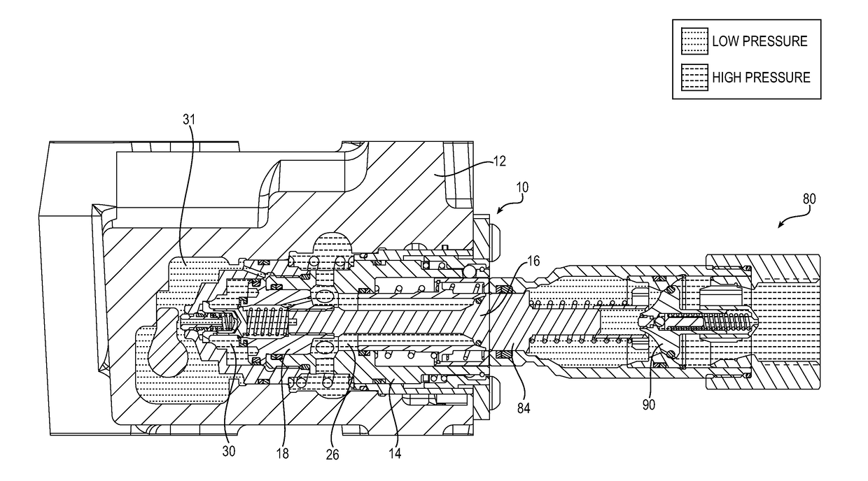
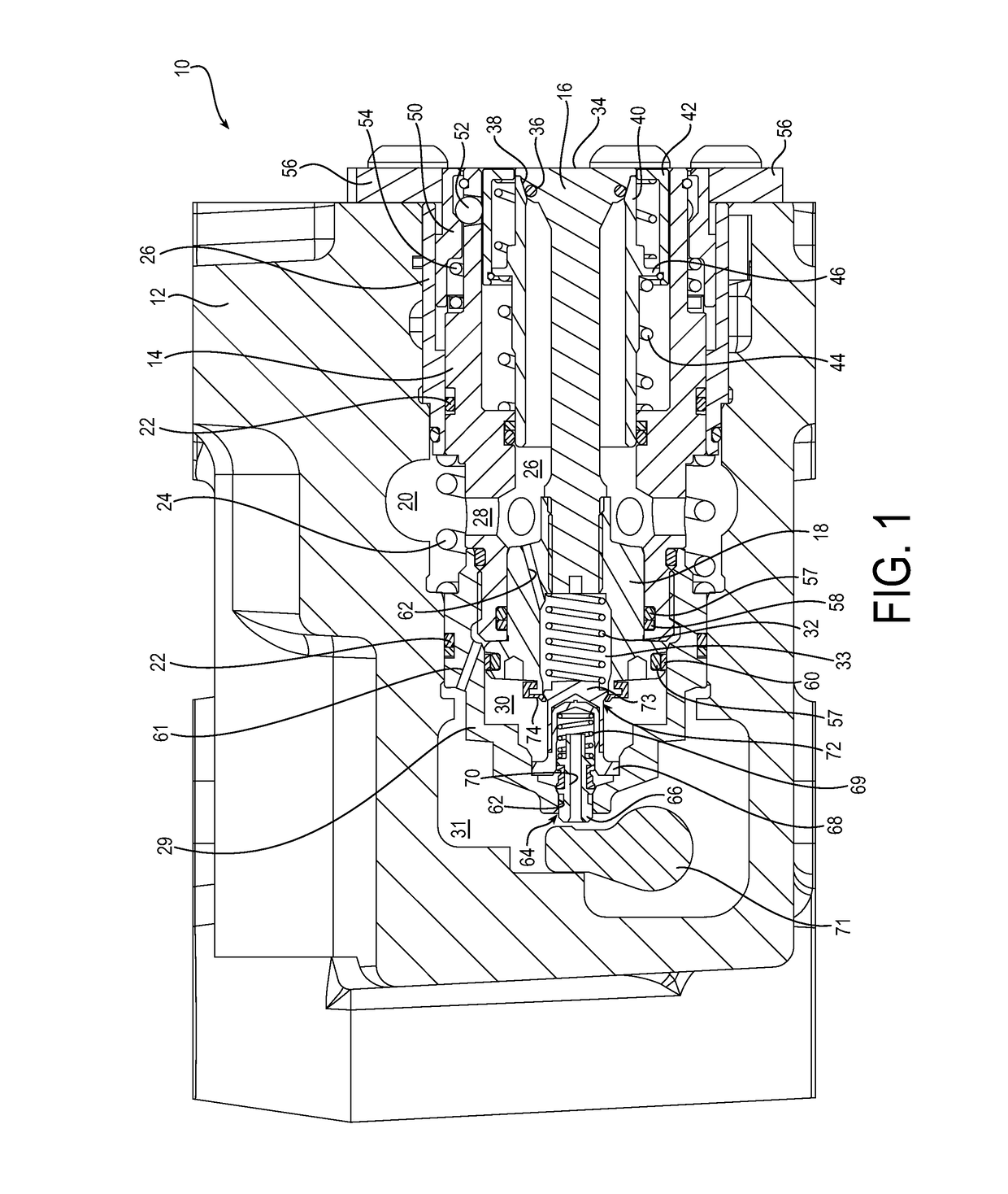
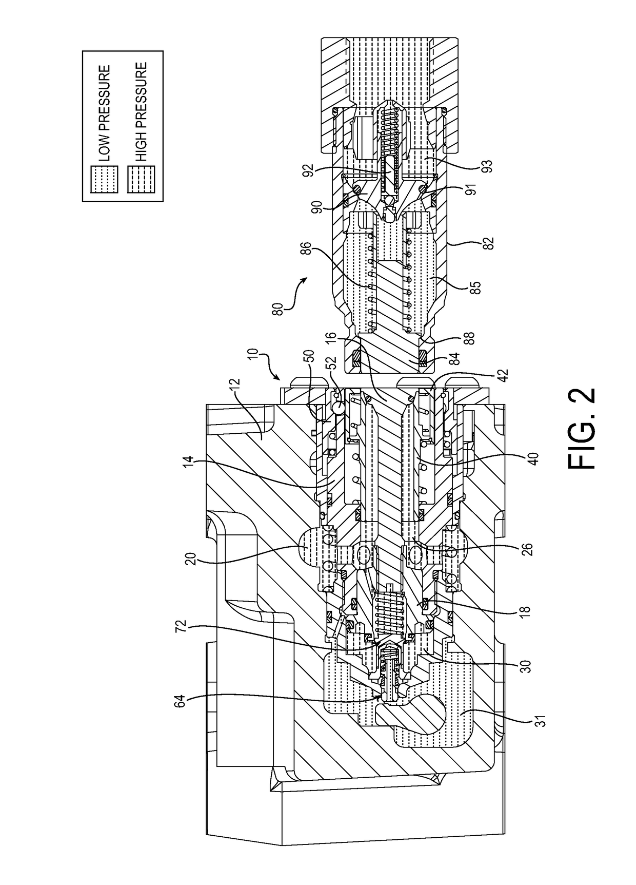
[0032]The principles of the present invention have particular application to quick-disconnect couplings, including a female coupler, or socket, and a corresponding male coupler, or nipple. The female coupler may be a casting mounted coupler, or cartridge, that may be used to connect the hydraulic system of an agricultural tractor with attachable implements, and thus will be chiefly described in this context. However, those skilled in the art will appreciate that the coupling may be used in other applications where it is desirable to provide safe connect or disconnect under pressure, while providing minimal spillage of operating fluid during the coupling or uncoupling between the couplers.

[0033]In the discussion above and to follow, the terms “upper”, “lower”, “top”, “bottom,”“end,”“inner,”“left,”“right,”“forward,”“rearward,”“horizontal,”“vertical,” etc. refer to an exemplary female coupler as viewed in a horizontal position, as shown in FIG. 1, for example. This is done realizing th...


PUM


Abstract

A quick connect/disconnect coupling having a female coupler and a corresponding male coupler. The female coupler has a non-spill configuration and includes a housing and a valve body slidably movable in the housing. A valve member is slidably movable in the valve body toward and away from a valve seat, the valve member being configured to engage the male coupler. A piston is interposed between a main cavity and a trap chamber of the female coupler. The piston may be fixed to the valve member for common movement, and may include an internal flow passage for enabling fluid connection between the main cavity and trap chamber. A check valve may allow fluid flow from the trap chamber to the main cavity when the trap chamber pressure is greater than the main cavity pressure. A locking collar may be independently movable of the valve body to reduce the force required to connect the couplers.

Description

RELATED APPLICATIONS[0001]This application claims the benefit of U.S. Provisional Application No. 62 / 256,878 filed Nov. 18, 2015, which is hereby incorporated herein by reference in its entirety.FIELD OF INVENTION[0002]The present invention relates generally to quick connect / disconnect couplings and, more particularly, to a non-spill female coupler for pressurized fluid lines.BACKGROUND[0003]Quick connect couplings are used, for example, to connect hoses in hydraulic fluid lines. A typical application is on agricultural tractors to connect the tractor hydraulic system with attachable implements. The tractor typically includes one or more female coupler sockets, while the implements include one or more male coupler nipples.[0004]Over the years changes have occurred in these systems which have required changes and performance improvements in the couplings. It is typically desirable for these couplings to connect regardless of trapped pressures within either the male or female side. It...

Claims


Application Information

Patent Timeline
IPC IPC(8): F16L37/34F16L55/07
CPCF16L55/07F16L37/34F16L37/32
Inventor FONER, BRIAN KEITH
Owner PARKER INTANGIBLES LLC
Why Eureka
Try Eureka