Image reading apparatus

a technology of image reading and reading apparatus, applied in the direction of electrical apparatus, pictoral communication, etc., can solve the problems of affecting the resolution of the image reading apparatus, the effect of reducing the influence of gaps and simple and inexpensive arrangemen

Inactive Publication Date: 2008-09-04
CANON KK
View PDF9 Cites 1 Cited by
  • Summary
  • Abstract
  • Description
  • Claims
  • Application Information

AI Technical Summary

Benefits of technology

[0008]The present invention has been made in consideration of the above situation, and has as its object to reduce the influence of gaps between photoelectric conversion element arrays on a read image by a simple and inexpensive arrangement.
[0010]It is another object of the present invention to minimize defocusing caused by variation in accuracy of parts and to prevent defocusing caused by lifting of an original by a simple and inexpensive arrangement.

Problems solved by technology

However, when a function of reading a transparent original such as a photographic film is to be imparted to an image reading apparatus, joints pose a problem.
Additionally, the image reading apparatus which reads a transparent original using photoelectric conversion elements has a poorer resolution at an end portion than at the central portion with respect to the main scanning direction because of its optical system structure.
In this case, even a very small shift of the film from the focal point of the contact type image read sensor can result in a decrease in resolution because of a small depth of field.

Method used


Image

  • Image reading apparatus
  • Image reading apparatus
  • Image reading apparatus

Examples


first embodiment

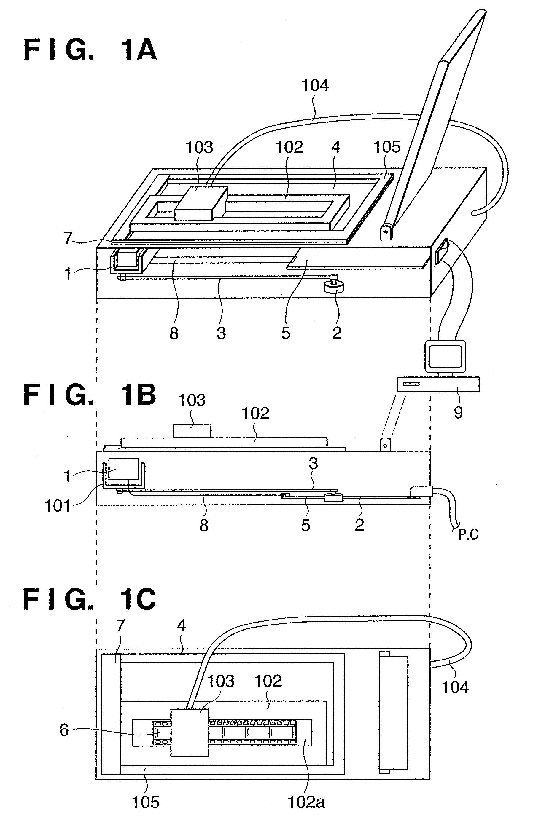
[0028]FIGS. 1A to 1C are views showing the arrangement of an image reading apparatus according to the present invention. FIG. 1A is a perspective view, FIG. 1B is a side view, and FIG. 1C is a plan view. Referring to FIGS. 1A to 1C, reference numeral 1 denotes an image reading unit; 2, a stepping motor; 3, a driving belt; 4, an original glass plate; 5, a control board; 6, a 35-mm photographic film; 7, an original regulating plate which also serves as a white reference plate; 8, a flat cable; 9, an external computer; 101, a carriage to which the image reading unit 1 is attached; 102, a film holder which is detachable from the image reading apparatus and stabilizes the 35-mm photographic film 6; 103, a film light source unit detachable from the image reading apparatus; 104, a cable which connects the film light source unit 103 to the control board 5; and 105, an original regulating plate.

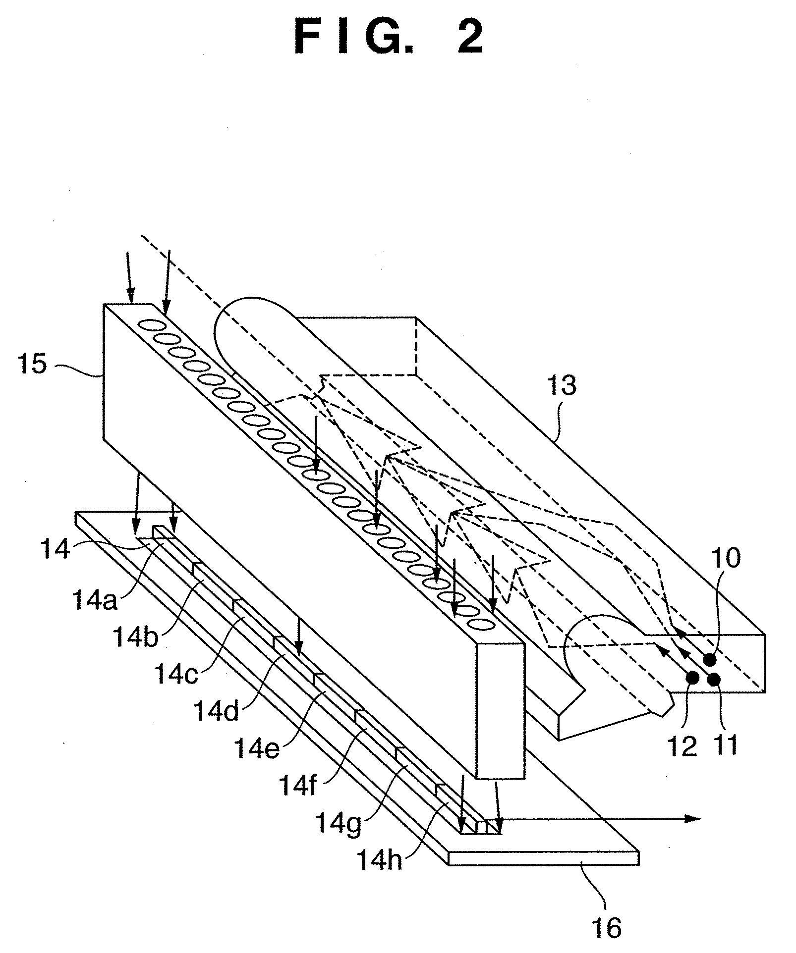
[0029]FIG. 2 is a perspective view showing the arrangement of the image reading unit 1. Reference ...

second embodiment

[0041]the present invention will be described next.

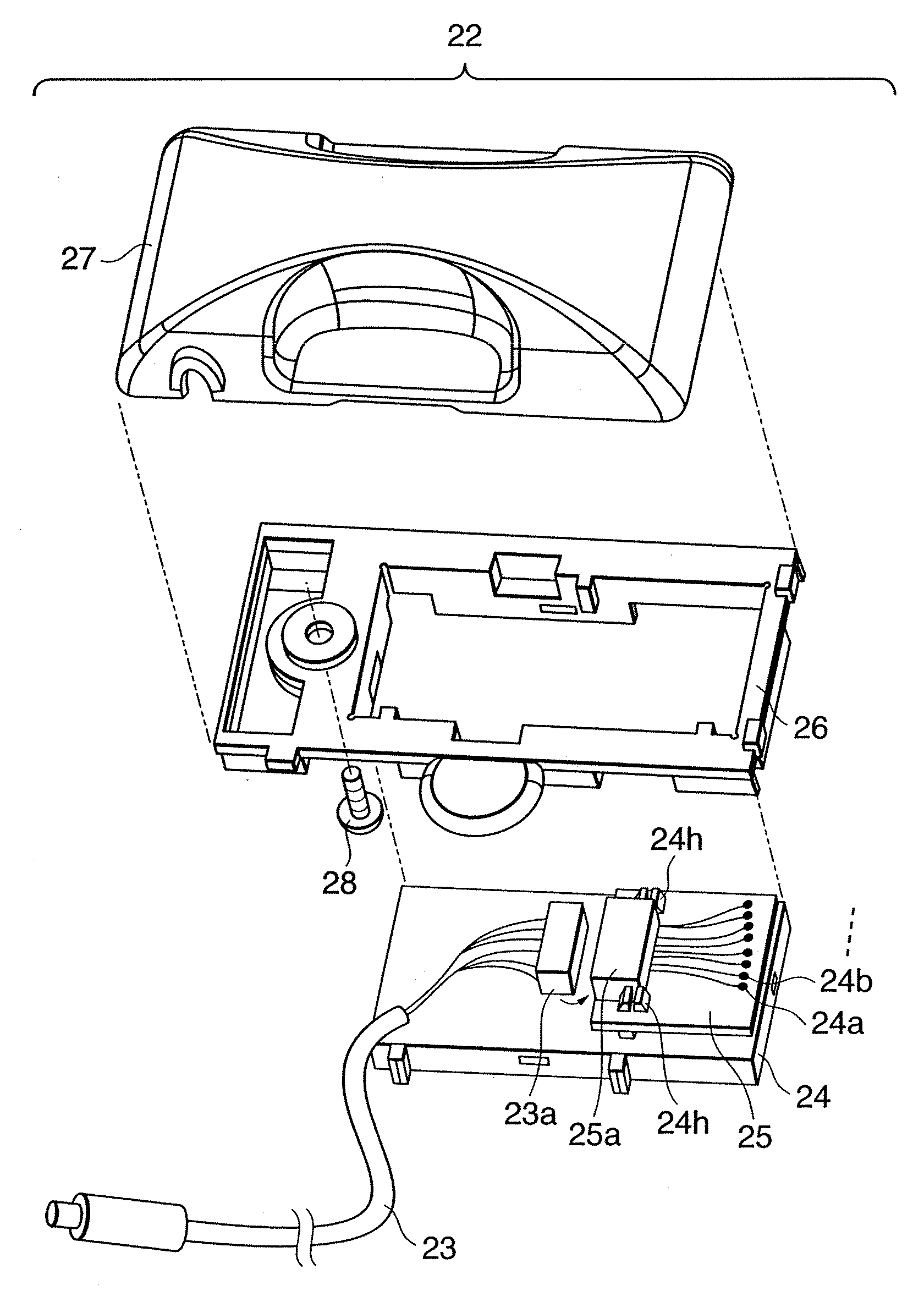
[0042]FIG. 5 is a partially cutaway perspective view showing the arrangement of an image reading apparatus according to the second embodiment of the present invention. Referring to FIG. 5, reference numeral 21 denotes a film holder detachable from the image reading apparatus; 22, a transparent original irradiation unit; 23, a cable; 200, a scanner main body; 201, a base frame; 202, an original glass plate; 203 and 204, glass frames; 210, an image reading unit; 220, a platen cover; and 221, a hinge of the platen cover.

[0043]The image reading unit 210 has the same arrangement as that of the image reading unit described in the first embodiment with reference to FIG. 2. The image of an object (not shown) placed on the original glass plate 202 can be read in the same way as described above in the first embodiment.

[0044]A case wherein a 35-mm photographic film F as a transparent original is to be read in the second embodiment will be desc...


PUM


Abstract

To set at least the main portion of a read original on an image reading apparatus while avoiding a discontinuous portion, the position of the discontinuous portion of photoelectric conversion element arrays is indicated, or an original holder to be used to set the original while avoiding the discontinuous portion is arranged.

Description

CROSS-REFERENCE TO RELATED APPLICATIONS[0001]This application is a continuation of pending U.S. patent application Ser. No. 10 / 422,510, filed Apr. 24, 2003, to which priority under 35 U.S.C. §120 is claimed. This application claims a benefit of priority based on Japanese Patent Application Nos. 2002-126162 filed on Apr. 26, 2002 and No. 2003-100635 filed on Apr. 3, 2003, the entire contents of all of which are hereby incorporated by reference as if fully set forth herein.FIELD OF THE INVENTION[0002]The present invention relates to an image reading apparatus which reads an image using photoelectric conversion element arrays and, more particularly, to an image reading apparatus which uses an image read sensor having photoelectric conversion element arrays with discontinuous portions.BACKGROUND OF THE INVENTION[0003]Conventionally, there is an image reading apparatus which reads an image on photographic printing paper or a magazine using an image reading unit having a plurality of phot...

Claims


Application Information

Patent Timeline
Patent Type & Authority Applications(United States)
IPC IPC(8): H04N1/04H04N1/10H04N1/00H04N1/107H04N1/193
CPCH04N1/1013H04N1/193H04N2201/0446H04N2201/0418H04N2201/0408
Inventor AMIMOTO, MITSURUYAMAUCHI, TSUYOSHI
Owner CANON KK
Why Eureka
Try Eureka