Variable valve train system for internal combustion engine

a technology of internal combustion engine and variable valve train, which is applied in the direction of valve arrangement, machine/engine, output power, etc., can solve the problems of substantial increase in cost, insufficient lubrication of the engagement section between the gears, and considerable complexity of the oil supply system, so as to improve the durability and reliability of the transmission mechanism, reduce the cost of operation, and reduce the effect of friction

Active Publication Date: 2010-06-08
MITSUBISHI MOTORS CORP
View PDF13 Cites 1 Cited by
  • Summary
  • Abstract
  • Description
  • Claims
  • Application Information

AI Technical Summary

Benefits of technology

[0012]According to the present invention, as the camshaft is driven, the lubricant adhering to the endless elongate member scatters therefrom. Since the engagement section of the transmission mechanism is arranged at a position where the engagement section can receive the lubricant scattered from the endless elongate member, fresh lubricant can be continuously supplied to the engagement section without the need for an additional complicated and costly lubrication system such as oil passages. The transmission mechanism can be lubricated with the use of a simple and inexpensive arrangement. Accordingly, wear of the engagement section is restrained, improving the durability and reliability of the transmission mechanism, and also since friction of the engagement section is reduced, the response characteristic of the transmission mechanism improves. Further, the transmission mechanism and the actuator therefor can be made compact in size.

Problems solved by technology

The engagement section between gears, in particular, is likely to be insufficiently lubricated because the gears are applied with large valve reaction force from the control shaft or, in a steady state, kept in a fixed orientation.
Thus, the oil supply system is considerably complicated in structure and substantially increases costs.

Method used


Image

  • Variable valve train system for internal combustion engine
  • Variable valve train system for internal combustion engine
  • Variable valve train system for internal combustion engine

Examples


Embodiment Construction

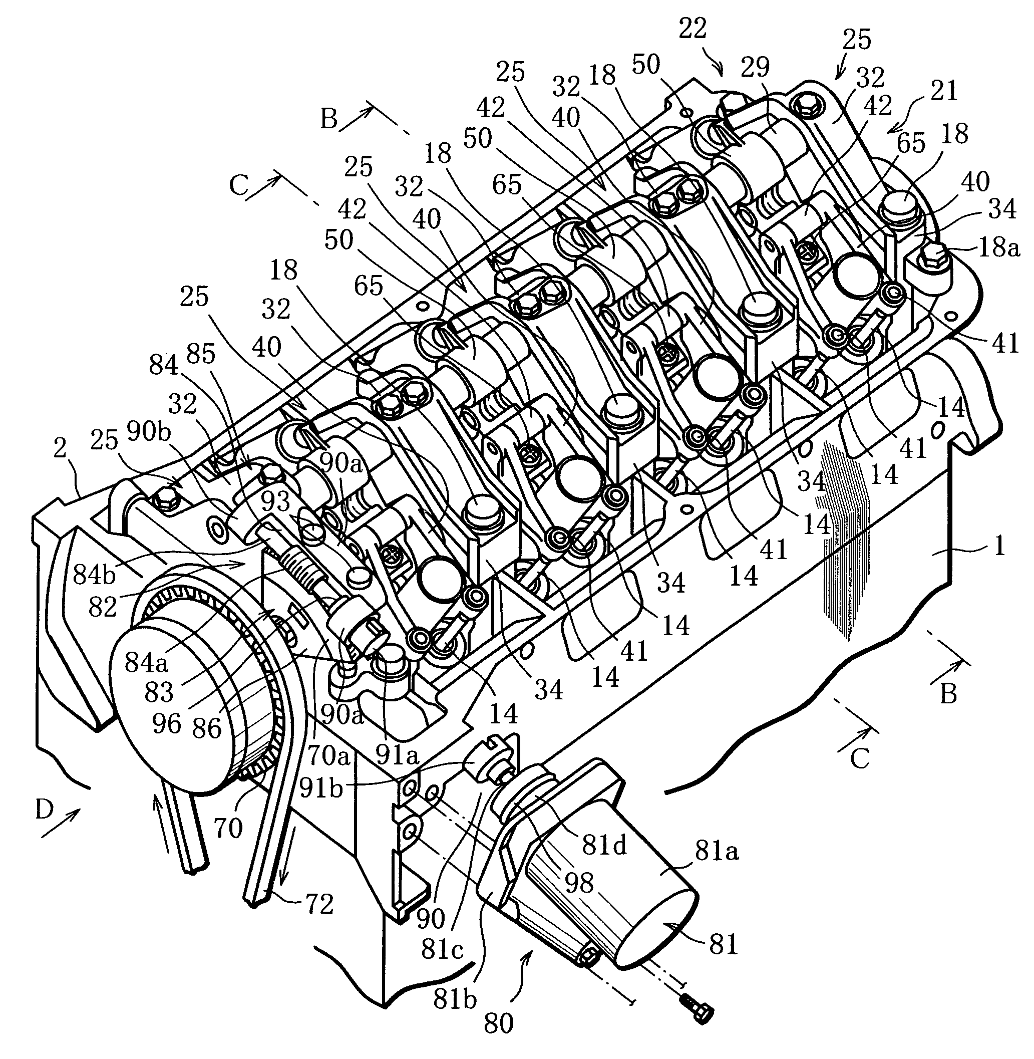
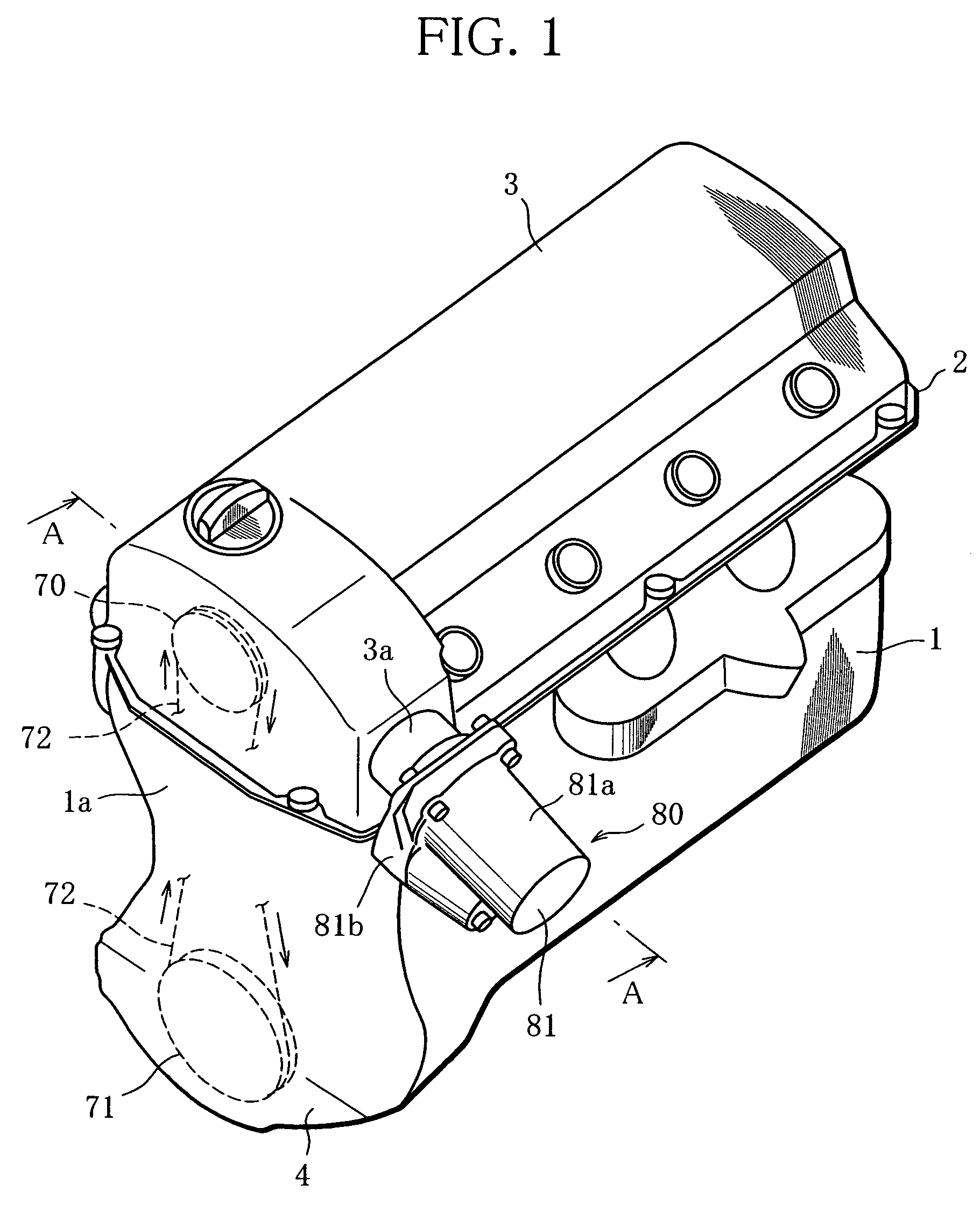
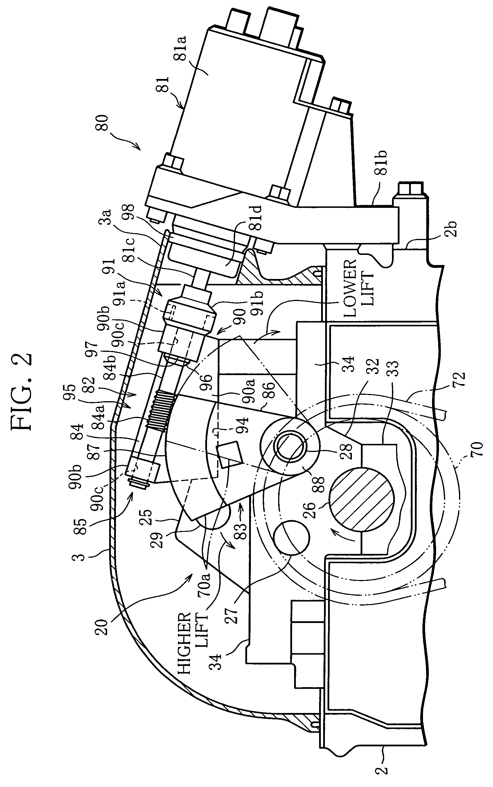
[0023]An embodiment of the present invention will be hereinafter described with reference to FIGS. 1 to 8, wherein FIG. 1 is a perspective view of an internal combustion engine, for example, an in-line, four-cylinder reciprocating gasoline engine, FIG. 2 is a sectional view take along line A-A in FIG. 1, FIG. 3 is a perspective view of the engine from which a rocker cover and a timing chain cover, shown in FIG. 1, are detached, FIG. 4 is an exploded perspective view of the engine from which a variable valve train system shown in FIG. 3 is detached, FIG. 5 is a sectional view of the variable valve train system taken along line B-B in FIG. 3, FIG. 6 is a sectional view of the variable valve train system taken along line C-C in FIG. 3, and FIGS. 7 and 8 show a transmission mechanism.

[0024]In FIG. 1, reference numeral 1 denotes a cylinder block constituting an engine body; 2 denotes a cylinder head placed over the cylinder block 1; 3 denotes a rocker cover covering an upper part of the ...


PUM


Abstract

A variable valve train system for an internal combustion engine wherein the engagement section of a transmission mechanism is lubricated by means of an existing part for driving a variable valve actuation mechanism. Gears forming the engagement section of the transmission mechanism are arranged at a position where the engagement section is lubricated with a lubricant scattered from an endless elongate member for driving a camshaft. The transmission mechanism can therefore be lubricated without the need for additional use of a lubricant passage and its associated elements, besides the existing parts for driving the variable valve actuation mechanism.

Description

BACKGROUND OF THE INVENTION[0001]1. Field of the Invention[0002]The present invention relates to a variable valve train system for continuously controlling the valve driving output of an internal combustion engine.[0003]2. Description of the Related Art[0004]Reciprocating engines (internal combustion engines) mounted on motor vehicles are generally equipped with a variable valve train system attached to the cylinder head for continuously controlling the characteristics of at least intake valves, to control the exhaust gas emitted from the engine and lower the pumping loss.[0005]Many of such variable valve train systems employ a variable valve actuation mechanism whereby the lift amount of at least the intake valves is continuously varied to adjust the amount of intake air. The variable valve actuation mechanism generally comprises the combination of a device for providing a valve driving output based on the displacement of an intake cam fitted on the camshaft, and a device for conti...

Claims


Application Information

Patent Timeline
Patent Type & Authority Patents(United States)
IPC IPC(8): F01L1/34
CPCF01L1/022F01L1/181F01L13/0021F01L1/024F01L1/20F01L2820/032F01L2013/0068F01L2103/01F01L2105/00F01L2800/13F01L2001/0535F01L2303/01F01L2305/00F01L13/00F02D13/00
Inventor TANABE, MIKIOYOSHIKA, DAISUKE
Owner MITSUBISHI MOTORS CORP
Why Eureka
Try Eureka