Temperature detection circuit for recording head and recording device therewith

a temperature detection circuit and recording head technology, applied in the field of image recording devices, can solve the problems of loss of equilibrium, conventional temperature detection circuits are susceptible to noise, and the detection circuit is difficult to make an effective use of the dynamic range of a/d converters, etc., and achieve the effect of correct detecting the temperature of the recording head and simple and inexpensive arrangemen

Inactive Publication Date: 2007-07-19
CANON KK
View PDF1 Cites 0 Cited by
  • Summary
  • Abstract
  • Description
  • Claims
  • Application Information

AI Technical Summary

Benefits of technology

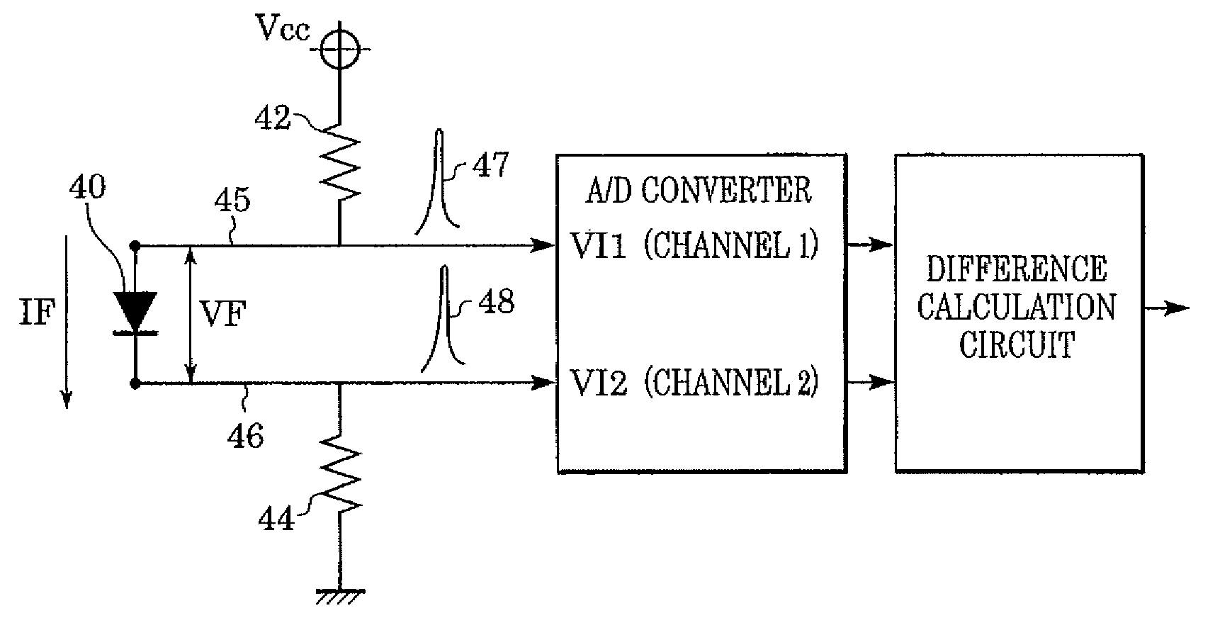
[0023] The present invention is directed to a recording head that performs recording using thermal energy and capable of correctly detecting temperature of the recording head with a simple and inexpensive arrangement.

Problems solved by technology

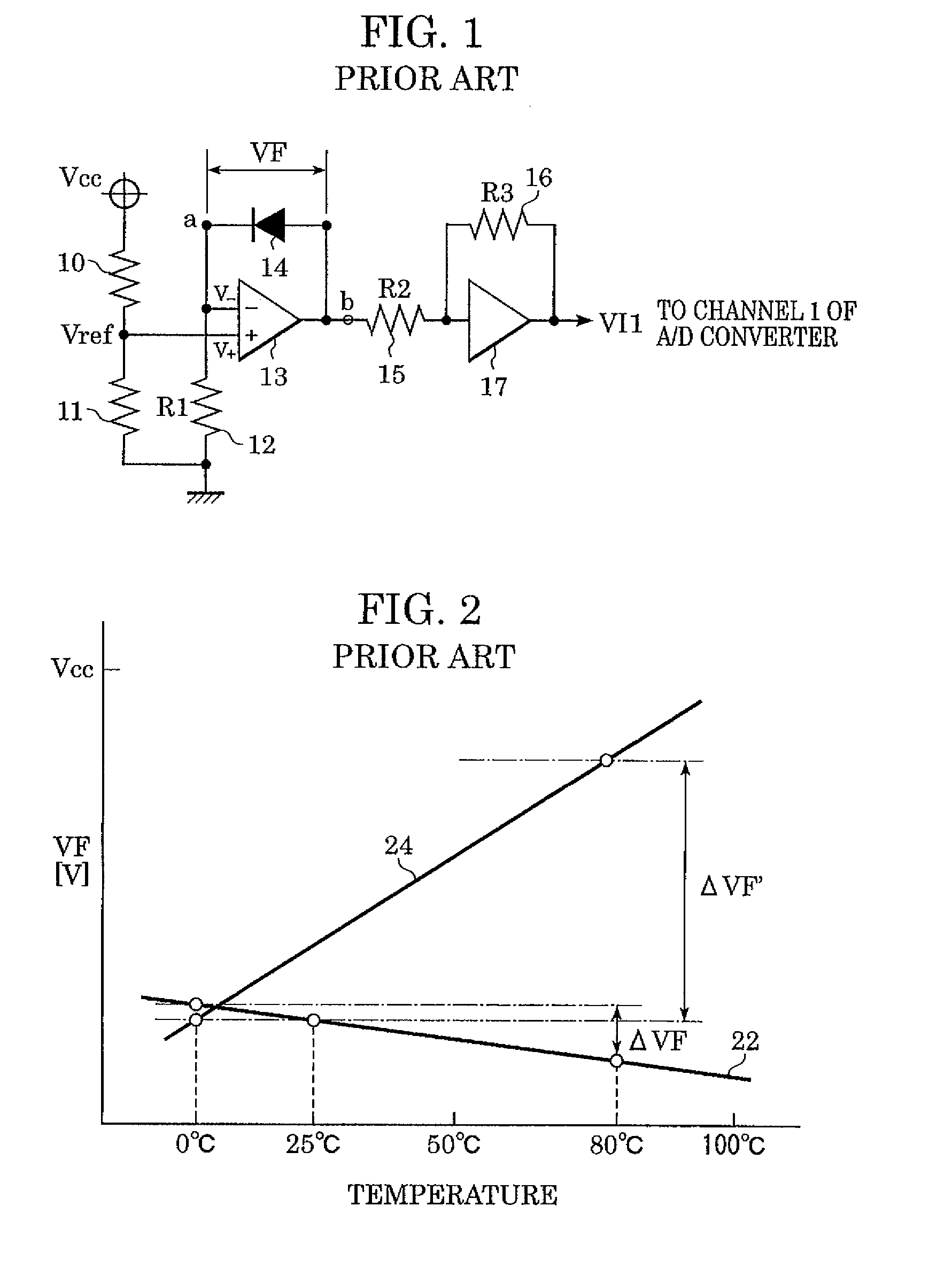
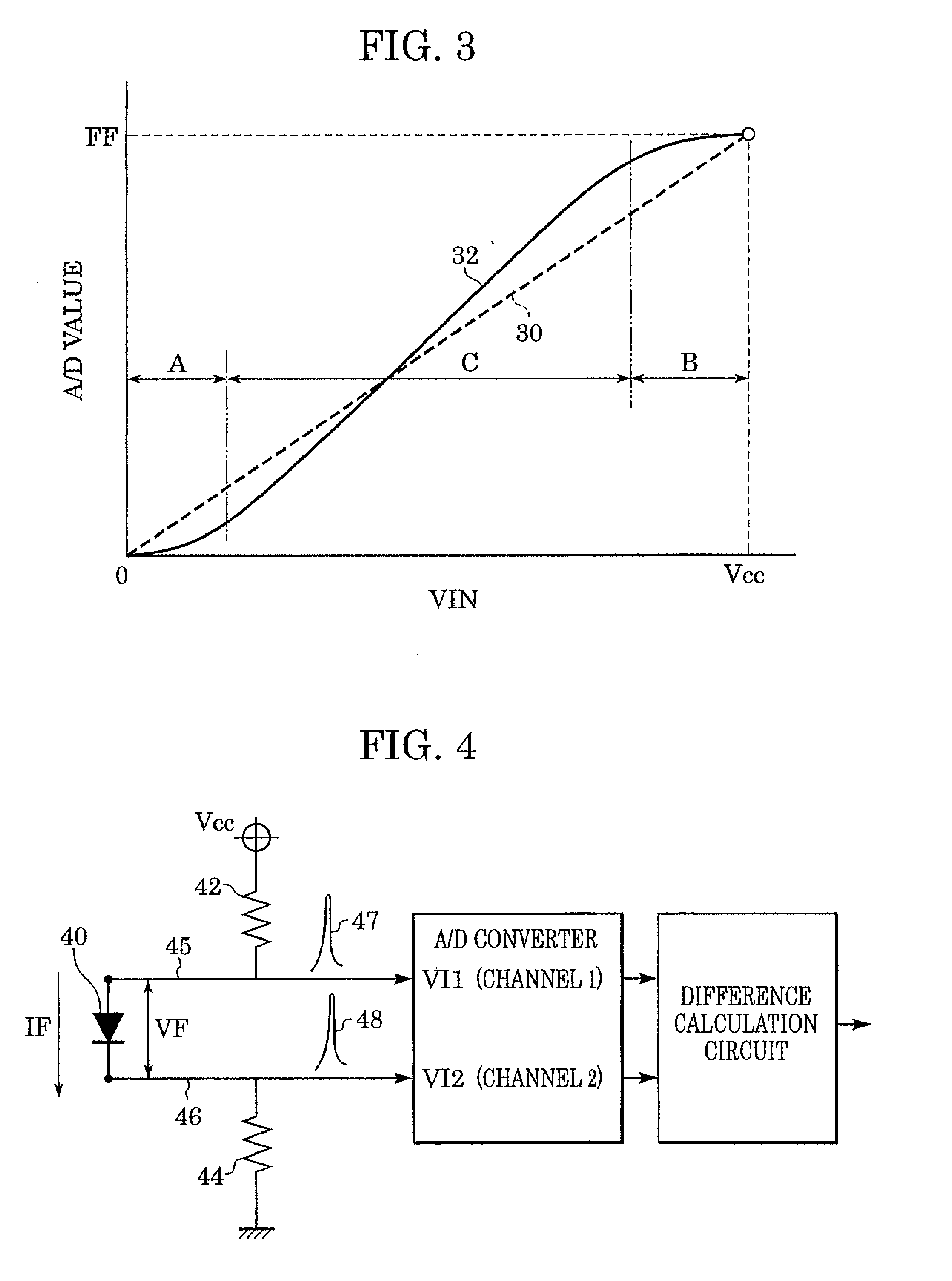
This results in utilizing only a range corresponding to about 5% of the dynamic range 2.5 V. In this way, the conventional temperature detection circuit is difficult to make an effective use of the dynamic range of the A / D converter.
This makes the conventional temperature detection circuit susceptible to noise.
However, when positive noise due to common mode noise or the like intrudes on the wiring connected to the diode sensor 14, the absolute value of V− may become higher than that of V−, thereby producing a loss of equilibrium.
In this manner, the construction as shown in FIG. 1 is susceptible to noise connected to the diode sensor 14, thereby causing a possibility of erroneously detecting an excessive temperature rise.
Although an A / D converter improved in such a tendency is available, it is generally expensive.

Method used


Image

  • Temperature detection circuit for recording head and recording device therewith
  • Temperature detection circuit for recording head and recording device therewith
  • Temperature detection circuit for recording head and recording device therewith

Examples


Embodiment Construction

[0039] Hereinafter, embodiments of the present invention will be described in detail with reference to the accompanying drawings. It is, however, to be understood that components set forth in these embodiment are illustrative, and that the present invention is not limited to the specific embodiments thereof except as defined in the appended claims.

[0040] In the description, the term “recording” (also referred to as “print” hereinafter) not only includes the formation of significant information such as characters and graphics, but also broadly includes the formation of images, figures, patterns, and the like on a recording medium, or the processing of the recording medium, irrespective of whether they are significant or insignificant, and whether they are visualized so as to be perceivable by humans.

[0041] The term “recording medium” not only includes a paper sheet used in common recording devices, but also broadly includes materials capable of accepting ink, such as a cloth, a pla...


PUM

PropertyMeasurementUnit
current valueaaaaaaaaaa
voltage drop VFaaaaaaaaaa
temperatureaaaaaaaaaa

Abstract

A recording head performing recording with thermal energy and having a temperature sensor. The sensor measures the temperature of the recording head with minimal susceptibility to common mode noise. The sensor includes a p-n junction of a semiconductor provided inside the recording head. Temperature detection is performed by converting a first voltage value at a P-side portion of the sensor and a second voltage value at a N-side portion of the sensor into respective digital data. A difference data of the respective digital data is calculated. Based on the difference data, the temperature of the recording head can be determined.

Description

CROSS REFERENCE TO RELATED APPLICATIONS [0001] This is a continuation of co-pending U.S. patent application Ser. No. 10 / 990,673 filed Nov. 16, 2004, which claims the benefit of Japanese Application 2003-386,940, filed Nov. 17, 2003, both of which are incorporated by reference herein in their entirety.BACKGROUND OF THE INVENTION [0002] 1. Field of the Invention [0003] The present invention relates to an image recording device, and more specifically to a temperature detection circuit that detects the temperature of a recording head performing image recording using thermal energy. [0004] 2. Description of the Related Art [0005] Recording devices that record information such as desired characters and images, on sheet-shaped recording media such as paper and films, are widely used as information output devices for word processors, personal computers, facsimiles, etc. [0006] As recording systems for recording devices, a variety of systems are known. Among them, the ink jet system has rece...

Claims


Application Information

Patent Timeline
Patent Type & Authority Applications(United States)
IPC IPC(8): G06K15/12G06F15/00G06K1/00B41J2/125B41J2/01B41J2/195G01K7/01
CPCB41J2/195B41J2/125
Inventor TAKAYANAGI, YOSHIAKI
Owner CANON KK
Why Eureka
Try Eureka