Varistor protection cover and varistor device

a technology for varistor devices and protection covers, which is applied in the field of protection covers, can solve the problems of circuit failure, circuit failure to work, and large amount of heat generated or even fire caught,

Inactive Publication Date: 2010-10-05
POWERTECH INDAL
View PDF6 Cites 13 Cited by
  • Summary
  • Abstract
  • Description
  • Claims
  • Application Information

AI Technical Summary

Benefits of technology

[0008]An object of the present invention is to provide a protection cover, which is made of ceramic or refractory material to bear high temperature generated when a varistor breaks down to catch fire and to further cover the fire therein, thereby preventing the fire from burning out application components around the metal oxide varistor. Moreover, accommodation portions and grooves for receiving temperature breakers are disposed on the protection cover to provide a better contact surface between the protection cover and the temperature breakers so that the temperature breakers can more accurately detect the temperature on the protection cover, hence reducing the occurrence of the situation of erroneous actions.
[0010]The present invention also provides a varistor device, which comprises a varistor module and a protection cover. The protection cover covers on the varistor module to avoid the influence brought about by high temperature or fire caused by a too high voltage across the varistor module.

Problems solved by technology

When the MOV continually receives a high voltage or the received voltage exceeds the bearable rated value, a large amount of heat will be generated or even fire is caught.
High temperature may cause abnormal operations of the circuit or even cause the circuit not to work, not mentioning the influence of fire to the electronic components.
The adhesion between a common MOV and the temperature breaker, however, is not good enough.
The temperature breaker cannot accurately detect the temperature because of the existence of gaps.
The situation that the temperature breaker does not work when the temperature is high enough to influence the circuit may arise.
Besides, when the temperature breaker is adhered onto the surface of the MOV, if the MOV is burned out instantaneously under a high voltage, the temperature breaker may also be burned out instantaneously and therefore cannot cut off the working power, hence being not able to exactly protect the circuit.

Method used


Image

  • Varistor protection cover and varistor device
  • Varistor protection cover and varistor device
  • Varistor protection cover and varistor device

Examples


fourth embodiment

[0036]FIG. 9 is an exploded perspective view of the varistor device according to the present invention. As shown in FIG. 9, an accommodation portion 92 is disposed on one side of the protection cover 9 to receive a temperature breaker 91. That is, whether the accommodation portion is disposed on one side or two sides of the protection cover to receive temperature breaker is not limited in the present invention.

fifth embodiment

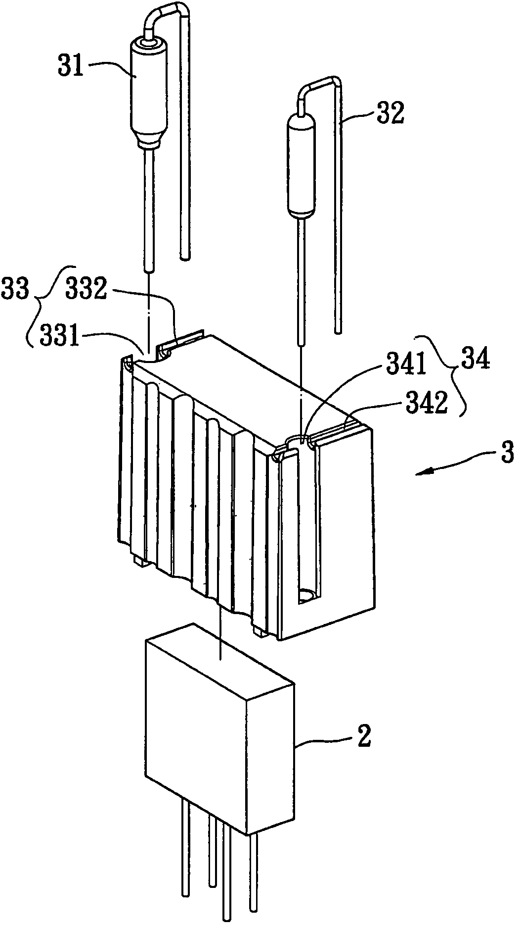
[0037]FIG. 10 is an exploded perspective view of the varistor device according to the present invention. As shown in FIG. 10, the first temperature breaker 31, the second temperature breaker 32 and the MOV module 2 are covered in a first protection cover 101 and a second protection cover 102. The first protection cover 101 and the second protection cover 102 have a first body accommodation groove 1031 and a second body accommodation groove 1032 to receive the first temperature breaker 31 and the second temperature breaker 32, respectively. If the varistor module 2 catches fire due to a continual high voltage, the fire can be controlled in the first protection cover 101 and the second protection cover 102. Moreover, when the first temperature breaker 31 and the second temperature breaker 32 detect the high temperature of fire, they can break the related power circuit connected with the varistor module 2 to achieve the object of protecting related components and circuits.

sixth embodiment

[0038]FIG. 11 is an exploded perspective view of the varistor device according to the present invention. As shown in FIG. 11, an accommodation groove 1131 is disposed in a first protection cover 111 and a second protection cover 112 to receive a temperature breaker 113 for protection.

[0039]To sum up, the protection cover of the present invention can have at least a temperature breaker (which is not necessarily disposed outside or inside the protection cover) to more directly and accurately detect the temperature, and can prevent the temperature breaker from being burned out by high temperature fire so that the temperature breaker can effectively accomplish the protection function.


PUM


Abstract

A protection cover used for avoiding the influence brought about by the temperature effect of a varistor is proposed. The protection cover is made of ceramic or refractory material, and is used to bear high temperature generated when a metal oxide varistor breaks down to catch fire and to further cover the fire therein, thereby preventing the fire from burning out application components around the metal oxide varistor. Moreover, accommodation portions and grooves for receiving temperature breakers are disposed on the protection cover to provide a better contact surface between the protection cover and the temperature breakers so that the temperature breakers can more accurately detect the temperature on the protection cover, hence reducing the occurrence of the situation of erroneous actions.

Description

BACKGROUND OF THE INVENTION[0001]1. Field of the Invention[0002]The present invention relates to a protection cover and, more particularly, to a protection cover used in varistors.[0003]2. Description of Related Art[0004]Common metal oxide varistors (MOV) can be classified into three categories: SiC, Si Zener diode and ZnO. Ceramic bipolar varistors formed by sintering ZnO powder at high temperatures have a nonlinear resistance-versus-voltage relation. They have a very high resistance that can block the passage of current at low voltages, but their resistance drops drastically to allow the passage of large currents at high voltages. This characteristic has been widely applied in the voltage regulation and the suppression of transient surge of electronic circuits and power systems such as communication equipments, consumer electronic products, industrial machines and power distribution and transmission devices.[0005]When the MOV continually receives a high voltage or the received vol...

Claims


Application Information

Patent Timeline
Patent Type & Authority Patents(United States)
IPC IPC(8): H01C7/10
CPCH01C7/102H01C7/126
Inventor CHOU, YI-HSIUNGLEE, YU-LUNG
Owner POWERTECH INDAL
Why Eureka
Try Eureka