Dynamoelectric machine

a dynamoelectric machine and dynamoelectric technology, applied in the direction of dynamoelectric components, electric motor control, cooling/ventilation arrangement, etc., can solve the problems of complex assembly process of such dynamoelectric machines, and achieve the effect of improving detection precision and assembly of dynamoelectric machines

Active Publication Date: 2009-12-15
MITSUBISHI ELECTRIC CORP
View PDF14 Cites 14 Cited by
  • Summary
  • Abstract
  • Description
  • Claims
  • Application Information

AI Technical Summary

Benefits of technology

[0005]The present invention aims to solve the above problems and an object of the present invention is to provide a dynamoelectric machine enabling stator winding temperature detecting precision of a temperature measuring means to be improved while also improving assembly of the dynamoelectric machine.
[0007]Using a dynamoelectric machine according to the present invention, assembly of the dynamoelectric machine is improved because it is not necessary to hold the temperature measuring means on the stator winding, and stator winding temperature detecting precision is improved because the stator winding temperature is estimated by calculating the sum of the measured temperature measured by the temperature measuring means and the correcting value for correcting the measured temperature.

Problems solved by technology

However, a separate guide for housing the temperature detecting element is required in such dynamoelectric machines in order to hold the temperature detecting element on the coil end portions, and since such guides are fixed to a stator, one problem has been that the guides must have complicated shapes such as notched portions, hooked portions, etc., making assembly processes for such dynamoelectric machines complicated.

Method used


Image

  • Dynamoelectric machine
  • Dynamoelectric machine
  • Dynamoelectric machine

Examples


embodiment 1

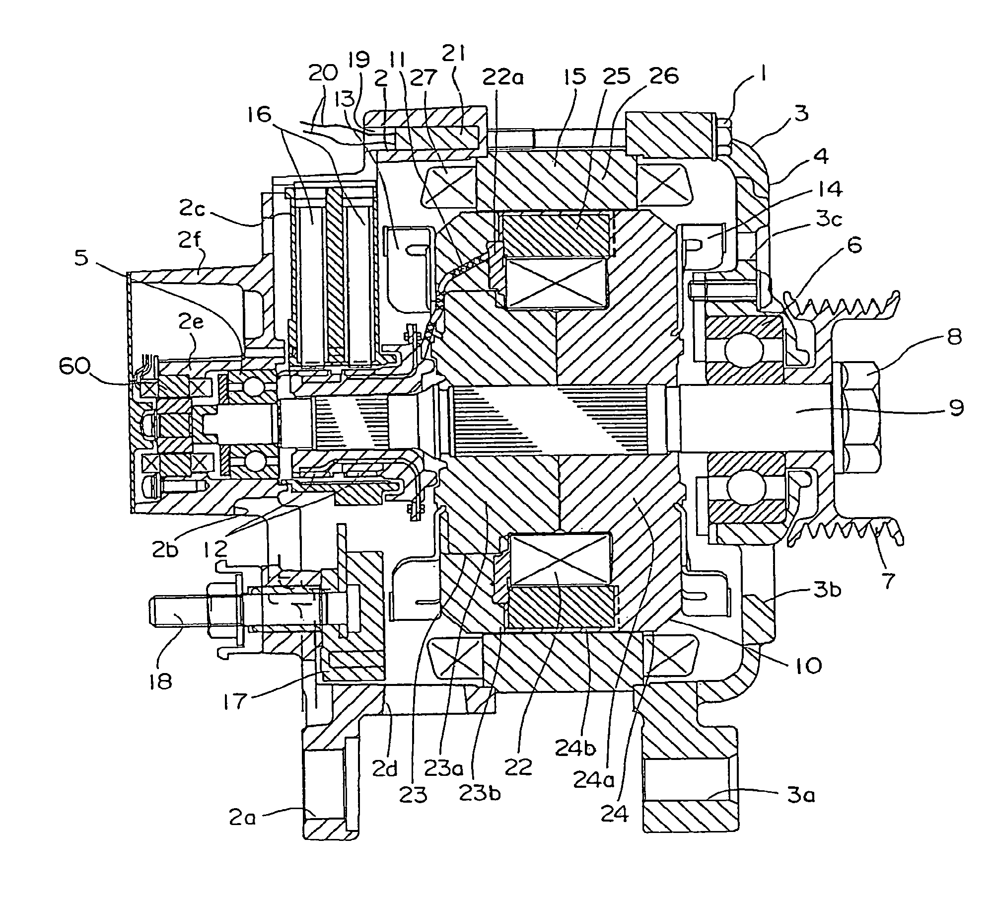
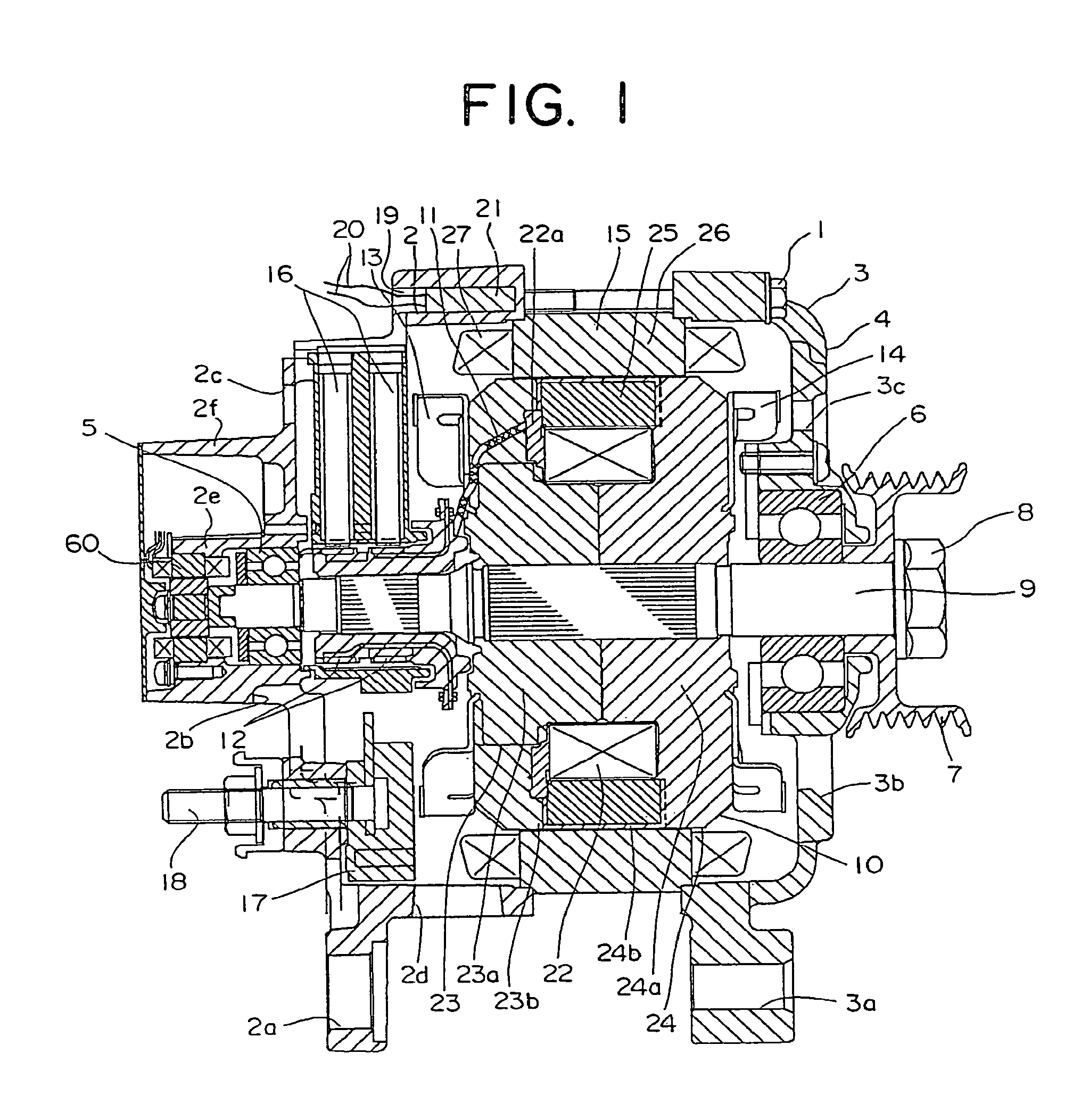
[0016]Embodiment 1 of the present invention will now be explained based on the drawings. FIG. 1 is a cross section showing a configuration of an automotive dynamoelectric machine according to Embodiment 1 of the present invention, and FIG. 2 is a cross section showing a temperature sensor mount portion and part of a vicinity of a stator from FIG. 1.

[0017]As shown in FIG. 1, an automotive dynamoelectric machine includes: a case 4 constituted by rear and front brackets 2 and 3 constituted by members that do not generate heat integrated by a bolt 1; a rotating shaft 9 supported inside the case 4 by means of bearings 5 and 6, a pulley 7 being fixed to a first end portion of the rotating shaft 9 by a nut 8; a rotor 10 fixed to the rotating shaft 9; slip rings 12 fixed to a second end portion of the rotating shaft 9, the slip rings 12 supplying an electric current to the rotor 10 by means of electric wires 11; cooling fans 13 and 14 fixed to first and second end surfaces of the rotor 10; ...

embodiment 2

[0054]Configuration and operation of an automotive dynamoelectric machine according to Embodiment 2 of the present invention are similar to those of Embodiment 1, but a method for calculating a temperature difference ΔT between a stator winding temperature Ts and a temperature Th at a temperature sensor 21 is different.

[0055]Here, since an amount of heat Qa generated by a single phase portion of a stator winding is given by Qa=R×lac2, where R is resistance in the single phase portion of the stator winding, then temperature difference ΔT is determined by a second-order function of line current flowing into the stator winding 27, which is a major reason for temperature increases in the stator winding 27.

[0056]Specifically, Tsa=Th+ΔT, and if we let ΔT=α×lac2, where α is a constant, the stator winding temperature estimated value Tsa can be calculated from the temperature Th at the temperature sensor 21 using a second-order function of the effective line current value lac for the tempera...

embodiment 3

[0064]Configuration and operation of an automotive dynamoelectric machine according to Embodiment 3 of the present invention are similar to those of Embodiments 1 and 2, but the stator winding temperature estimated value Tsa is corrected by being averaged over time.

[0065]Specifically, Tsb=((Tsa)+K) / (N+1), Tsa=Th+ΔT, and if we let ΔT=α×lac2, where α is a constant, a corrected stator winding temperature estimated value Tsb can be calculated by calculating and correcting a stator winding temperature estimated value Tsa from the temperature Th at the temperature sensor 21.

[0066]Here, the temperature difference ΔT is a second-order function of the line current lac, K is a sum of Tsa for the preceding X seconds, and N is the number of stator winding temperature estimated values estimated by the temperature sensor 21 for the preceding X seconds (i.e., the number of the temperature measurement values at the temperature sensor 21 for the preceding X seconds).

[0067]FIG. 6 is a graph showing s...


PUM


Abstract

A dynamoelectric machine enabling stator winding temperature detecting precision of a temperature measuring means to be improved while also improving assembly of the dynamoelectric machine is provided.The dynamoelectric machine according to the present invention includes: a stator winding disposed in a stator; a temperature sensor for estimating a stator winding temperature of the stator winding; and a thermally-conductive bracket disposed between the stator winding and the temperature sensor. An estimated value of the stator winding temperature is calculated using a sum of a measured temperature measured by the temperature measuring means and a correcting value for correcting the measured temperature.

Description

TECHNICAL FIELD[0001]The present invention relates to a dynamoelectric machine in which stator winding temperature is estimated and detected.BACKGROUND ART[0002]In some conventional dynamoelectric machines, a guide for housing a temperature detecting element for detecting stator winding temperature is included, and the guide is held in direct contact with coil end portions of a winding. (See Patent Literature 1, for example.)Patent Literature 1[0003]Japanese Patent Laid-Open No. 2003-92858 (Gazette: pp. 2-5; FIG. 3)[0004]However, a separate guide for housing the temperature detecting element is required in such dynamoelectric machines in order to hold the temperature detecting element on the coil end portions, and since such guides are fixed to a stator, one problem has been that the guides must have complicated shapes such as notched portions, hooked portions, etc., making assembly processes for such dynamoelectric machines complicated.DISCLOSURE OF INVENTION[0005]The present inven...

Claims


Application Information

Patent Timeline
Patent Type & Authority Patents(United States)
IPC IPC(8): H02K11/00H02P29/00H02K9/06H02K19/22H02P29/02
CPCH02K11/0047H02K9/06H02K11/25
Inventor ISODA, HITOSHIASAO, YOSHIHITO
Owner MITSUBISHI ELECTRIC CORP
Why Eureka
Try Eureka