Heater with temperature detecting device and battery structure with the heater

a technology of temperature detecting device and battery structure, which is applied in the direction of electrochemical generators, cell components, cell component details, etc., can solve the problems of not being stably fixedly not being able to internally hold and the temperature measuring portion of the temperature detecting device cannot be stably held in contact with the heater, so as to minimize the uneven heating of the power generating element of the battery structure, reduce the variation in temperature distribution, and minimize the uneven heating

Active Publication Date: 2008-04-24
PANASONIC EV ENERGY CO LTD
View PDF14 Cites 13 Cited by
  • Summary
  • Abstract
  • Description
  • Claims
  • Application Information

AI Technical Summary

Benefits of technology

[0027]The battery structure with heater according to the present invention includes any one of the aforementioned heaters with temperature detecting device and is further configured such that the outer surface of the first or second metal sheet is placed in contact with at least part of the surface of the battery structure to be heated. Accordingly, the battery structure can be heated by the heater with temperature detecting device. In particular, the outer surface of the metal sheet can have a smaller variation in temperature distribution than the surface of the insulating resin film. When the battery structure is heated in a state where the outer surface of the first or second metal sheet is in contact with the heated surface of the battery structure, accordingly, uneven heating of the heated surface can be reduced. It is therefore possible to minimize uneven heating of the power generating element of the battery structure.
[0028]Further, the aforementioned heater with temperature detecting device can accurately detect the temperature of the heater by the temperature detecting device for long periods as mentioned above. When the temperature of the heater is controlled (e.g., ON-OFF control) by use of the temperature detecting device, the battery structure can be heated appropriately over long periods.

Problems solved by technology

However, this heater is very small in thickness and could not internally hold the temperature detecting device as in the above publication '087.
This may cause a problem that a temperature measuring portion of the temperature detecting device could not be held stably in fixedly contact with the heater.
Thus, the temperature of the heater could not be measured accurately in the long term.
However, when the temperature detecting device is fixed to the laminated heater including two insulating resin films with use of the mechanical fastening device, the two insulating resin films are likely to be deformed or distorted by the fastening power of the mechanical fastening device.
This may cause the surface of the laminated heater that makes contact with the temperature detecting device to be deformed or distorted, thus generating a gap between the temperature measuring portion of the temperature detecting device and the surface of the laminated heater.
Accordingly, the temperature detecting device may not accurately detect the temperature of the laminated heater.
Furthermore, after fastening, creep of the insulation resin film (i.e., a phenomenon in which deformation or distortion gradually increases over time) may affect a fastened portion, gradually decreasing the thickness of the fastened portion of the insulation resin film.
As a result, the fastening power will progressively go down, so that a gap is likely to be formed between the temperature measuring portion of the temperature detecting device and the surface of the laminated heater.
Consequently, the temperature detecting device may not detect the temperature of the laminated heater accurately in the long term.

Method used


Image

  • Heater with temperature detecting device and battery structure with the heater
  • Heater with temperature detecting device and battery structure with the heater
  • Heater with temperature detecting device and battery structure with the heater

Examples


Embodiment Construction

[0045]A detailed description of a preferred embodiment of a battery structure with heater (hereinafter, referred to as a “heater-equipped battery structure”) 10 according to the present invention will now be given referring to the accompanying drawings.

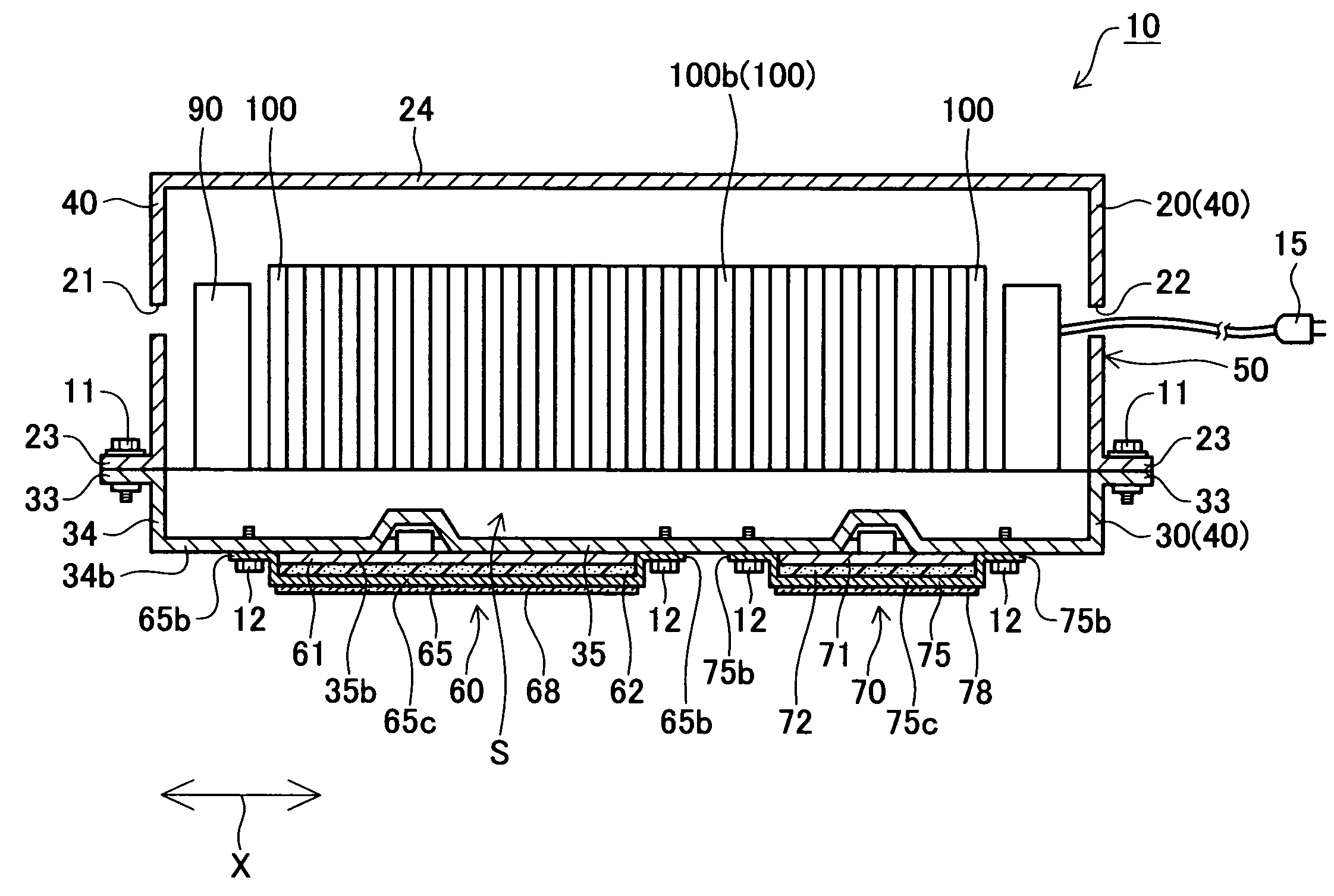
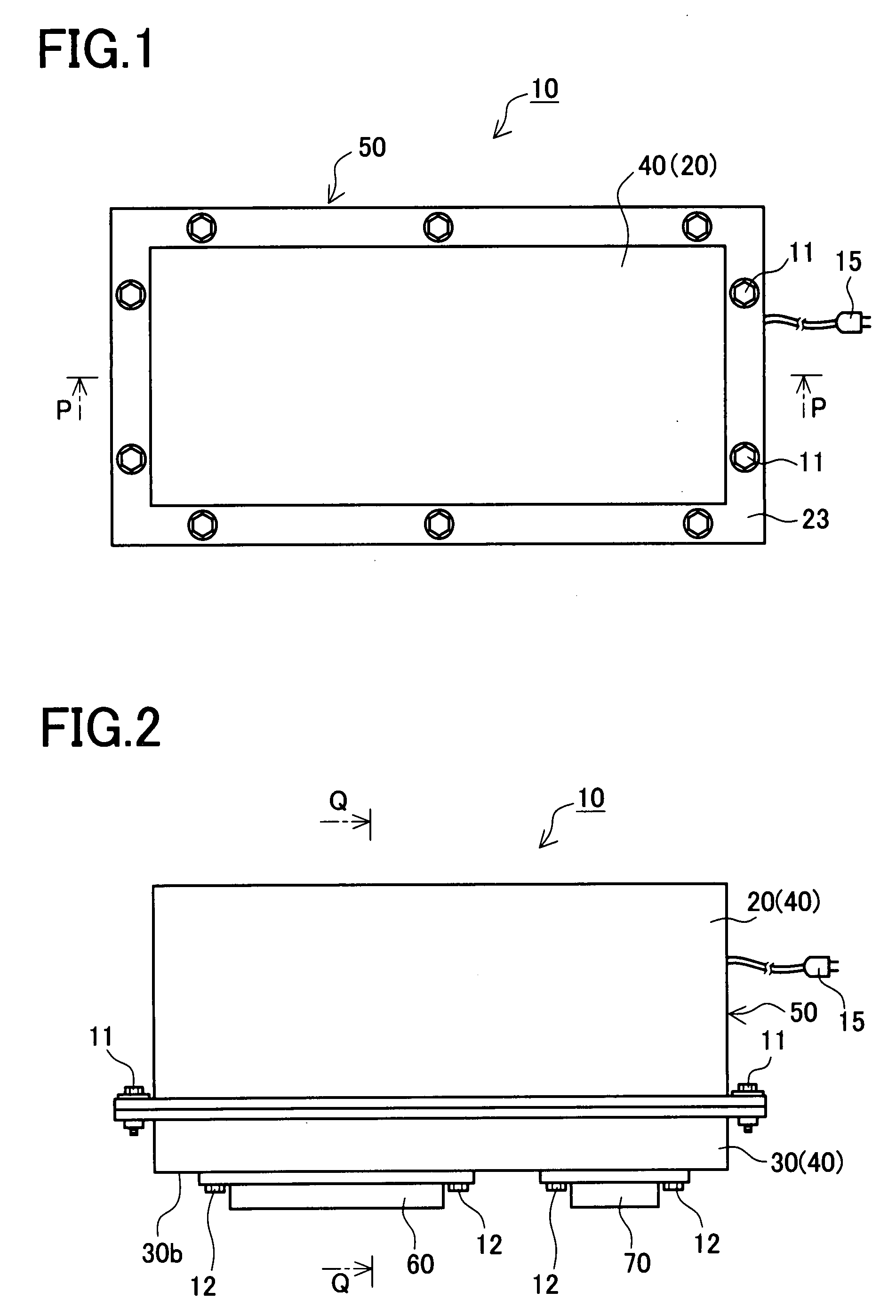
[0046]The heater-equipped battery structure 10 includes a battery pack 50, a first heater unit 60, and a second heater unit 70 as shown in FIGS. 1 and 2.

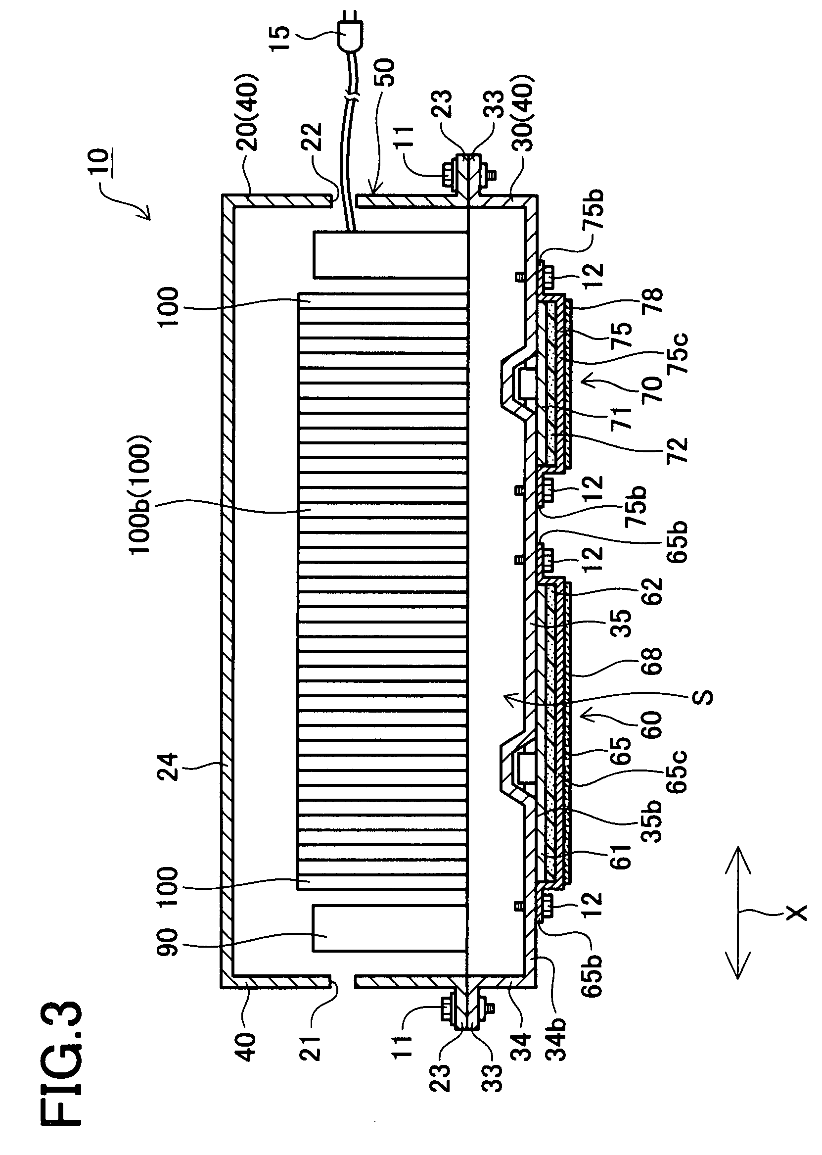
[0047]The battery pack 50 includes a housing case 40 constituted of a first housing member 20 and a second housing member 30, and a plurality of secondary batteries 100 (forty batteries in the present embodiment) housed in the housing case 40, as shown in FIG. 3. In the present embodiment, the battery pack 50 corresponds to a battery structure.

[0048]Each secondary battery 100 is a nickel-metal hydride storage sealed battery provided with a battery case 101, a positive terminal 161 and a negative terminal 162, as shown in FIG. 4. The battery case 101 has a resin case body 102 of a near...


PUM

PropertyMeasurementUnit
temperatureaaaaaaaaaa
strengthaaaaaaaaaa
thicknessaaaaaaaaaa

Abstract

An object of the present invention is to provide a heater with temperature detecting device, arranged to accurately detect the temperature of a laminated sheet heater by use of a temperature detecting device over long periods, and a battery structure including the heater with temperature detecting device. A first heater with temperature detecting device includes a first laminated sheet heater and a temperature sensor having a temperature measuring portion. The first laminated heater is constituted of first and second insulating resin films, a heater element, a first metal sheet, and a second metal sheet and includes a heater metallic section in which, of the first insulating resin film, the second insulating resin film, the heater element, the first metal sheet, and the second metal sheet, any one of only the first metal sheet and only a combination of the first metal sheet and the second metal sheet is arranged in a lamination direction of the laminated heater. The temperature sensor is fastened to the heater metallic section of the first laminated heater with a flat rivet and fixed to an outer surface of the first metal sheet with the temperature measuring portion is in contact with the first metal sheet.

Description

BACKGROUND OF THE INVENTION[0001]1. Field of the Invention[0002]The present invention relates to a heater including a laminated sheet heater and a temperature detecting device, and to a battery structure with this heater with temperature detecting device.[0003]2. Description of Related Art[0004]For fixing a temperature detecting device (a temperature sensor or the like) to the surface of a heater to detect the temperature of the heater, adhesive agents, adhesive tapes, or the like are often used as a fixing means.[0005]Jpn. unexamined patent publication No. 2004-356087 discloses a heater having a substrate, a heating element placed on the substrate, and a fixing material placed over the substrate in such a manner as to cover the heating element. This publication discloses in the first embodiment the heater that includes a temperature detecting device embedded therein with a fixing material as well as the heating element.[0006]Thinner heaters have been desired in recent years, increa...

Claims


Application Information

Patent Timeline
Patent Type & Authority Applications(United States)
IPC IPC(8): H05B1/00H01M2/10H01M10/60H01M10/615H01M10/617H01M10/647H01M10/6551H01M10/6571H01M10/658H05B3/20
CPCH05B3/30H05B1/0294
Inventor SUZUKI, MASAHIKOOKUDA, JUNTORII, YUJIUEMURA, YUKIEKANAMARU, KUNIO
Owner PANASONIC EV ENERGY CO LTD
Why Eureka
Try Eureka