Whole-temperature-range thermoelectric-field transmission electron microscope in-situ sample rod

An electron microscope and sample rod technology, applied in scanning probe technology, instruments, etc., can solve the problems of large heating area, large temperature drift, inaccurate temperature detection, etc., and achieve real-time accurate temperature detection, uniform temperature distribution, and reduced temperature. The effect of thermal drift

Inactive Publication Date: 2016-08-03
NINGBO INST OF MATERIALS TECH & ENG CHINESE ACADEMY OF SCI +1
View PDF4 Cites 13 Cited by
  • Summary
  • Abstract
  • Description
  • Claims
  • Application Information

AI Technical Summary

Problems solved by technology

The existing commercial or self-developed transmission electron microscope sample rods mostly adopt the rear end modification of the sample rod to achieve low temperature effects, but due to the size limitation of the transmission electron microscope sample rod, the temperature control range of the added components is small, or the temperature drifts Large, mainly the following problems:
[0005] 1. The existing low-temperature sample rod can only realize the low-temperature section, which has limitations for material research; it cannot be expanded by multiple physical fields, resulting in a single function, and it is impossible to realize the research of material properties under multi-field control
[0006] 2. The high-temperature sample rod generates a lot of heat, and the heating area is large, the sample drifts greatly, it is easy to damage the sample rod of the transmission electron microscope, and the life is short, which greatly limits the ability to observe and analyze the sample
[0007] 3. The temperature distribution of the sample stage is uneven, and the temperature detection is inaccurate due to the long distance between the temperature measuring element and the experimental sample

Method used


Image

  • Whole-temperature-range thermoelectric-field transmission electron microscope in-situ sample rod
  • Whole-temperature-range thermoelectric-field transmission electron microscope in-situ sample rod
  • Whole-temperature-range thermoelectric-field transmission electron microscope in-situ sample rod

Examples


Embodiment Construction

[0029] The present invention will be further described below in conjunction with the accompanying drawings of the description.

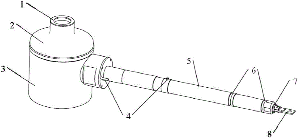
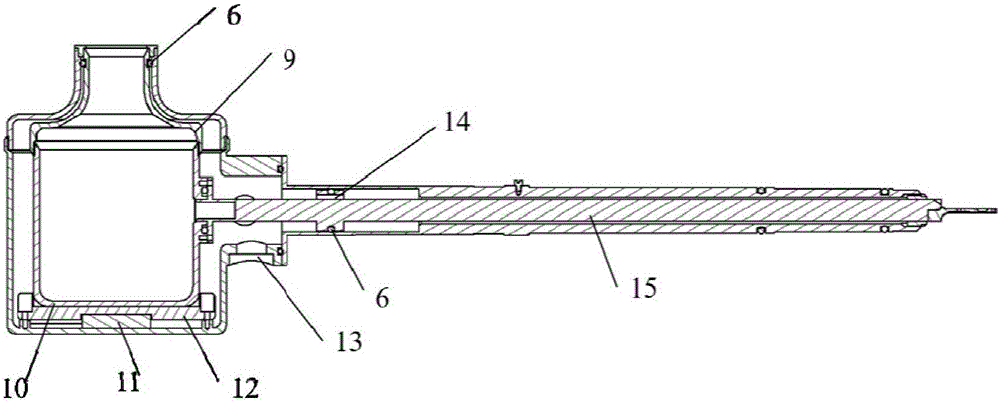
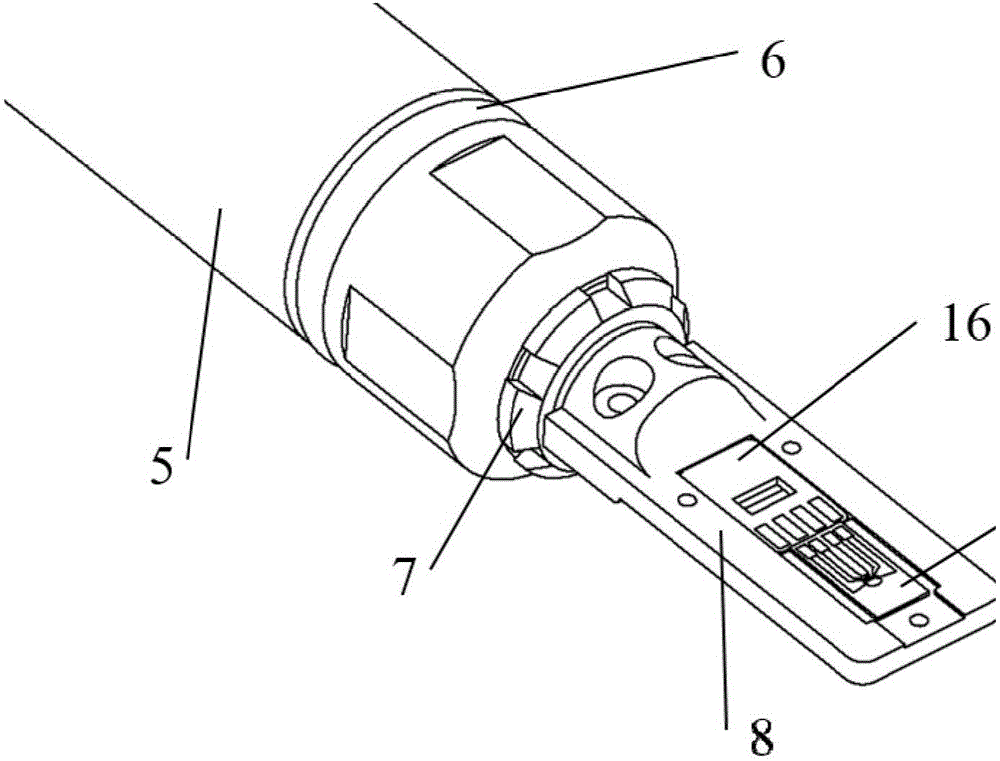
[0030] Such as Figure 1-3 As shown, it is a specific embodiment of the present invention. In this implementation, the in-situ sample rod of the thermoelectric two-field transmission electron microscope in the full temperature zone includes a DEWAR fixed ring 1, an upper part of the DEWAR outer tank 2, a lower part of the DEWAR outer tank 3, and a guide pin 4. Sample rod shell 5, sealing ring 6, fixing piece 7, sample rod head 8, upper part of DEWAR inner tank 9, lower part of DEWAR inner tank 10, heating module 11, fixing plate 12, vacuum electrical connector 13, wire hole 14, sample Rod inner rod 15, PCB adapter board 16 and in-situ test chip 17; the upper part 2 of the DEWAR outer tank is sealed and connected with the lower part 3 of the DEWAR outer tank, and the upper part 9 of the DEWAR inner tank passes through the DEWAR fixing ring 1 and the u...


PUM


Abstract

The invention discloses a whole-temperature-range thermoelectric-field transmission electron microscope in-situ sample rod which comprises a DEWAR fixing ring, a DEWAR outer tank upper portion, a DEWAR outer tank lower portion, guide pins, a sample rod shell, sealing rings, a fixing piece and a sample rod head, a DEWAR inner tank upper portion, a DEWAR inner tank lower portion, a heating module, a fixing plate, a vacuum electrical connector, a wire hole, a sample rod inner rod body, a PCB adapter plate and an in-situ test chip. Based on big-temperature-range design, electric signals can be directly added to a sample for conducting thermoelectric performance research in the sample material. The low-temperature and high-temperature cooling functions are achieved with liquid nitrogen, and refrigerating and cooling are achieved rapidly; a detachable mode is adopted for the sample rod head, the function of replacement and expansion is achieved, and single low temperature or high temperature is achieved or the whole-temperature-range is achieved at the same time; a chip microcell heating mode is adopted for a heating module, heat contact is lowered, and heat drift is reduced; design of enlarging the work microcell is utilized, a temperature measurement element is detected through resistance signal change, and real-time and accurate temperature detection can be achieved.

Description

technical field [0001] The invention belongs to the field of nanometer material measurement. The sample rod involves the observation of transmission electron microscope samples and the measurement of electricity and heat, and is mainly used for the research of phase transition and thermoelectric properties of materials at the micro-nano scale. Background technique [0002] Thermoelectricity and phase change are important properties of materials and devices, which can reflect many physical properties of materials and devices. The Seebeck effect discovered in 1823 and the Peltier effect discovered in 1834 provide a basis for the application of thermoelectric energy converters and thermoelectric refrigeration. Theoretical basis. Thermoelectric materials can convert a lot of waste heat energy generated in life, such as vehicle exhaust, gas emitted by factory boilers, etc., into energy that can be used again. The in-situ research on thermoelectric and phase change materials is ...

Claims


Application Information

Patent Timeline
Patent Type & Authority Applications(China)
IPC IPC(8): G01Q30/20
CPCG01Q30/20
Inventor 夏卫星郑修军彭勇关超帅胡阳杨保林张军伟马鸿斌薛德胜
Owner NINGBO INST OF MATERIALS TECH & ENG CHINESE ACADEMY OF SCI
Why Eureka
Try Eureka