
Optically determining the condition of goods

a technology of condition and goods, applied in the field of optically determining the condition of goods, can solve the problems of message imperceptible to the reader, message cannot be communicated to the reader, product is spoiled or otherwise unusable,

Active Publication Date: 2020-04-07
CHROMERA
View PDF7 Cites 4 Cited by
  • Summary
  • Abstract
  • Description
  • Claims
  • Application Information

AI Technical Summary

Benefits of technology

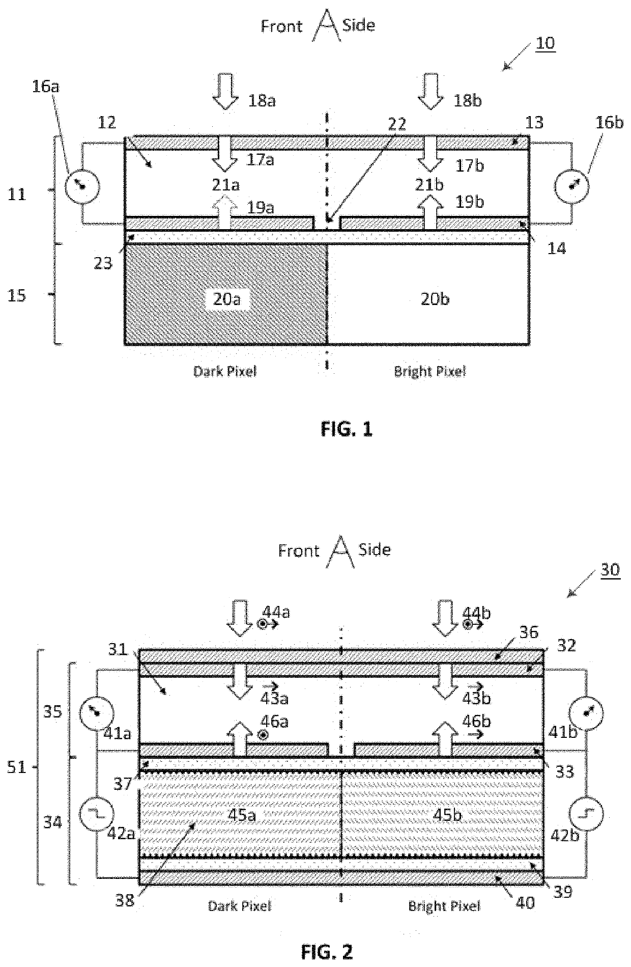
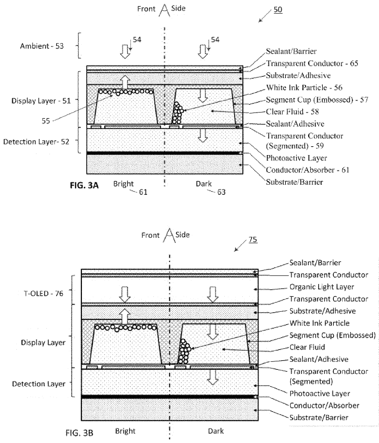
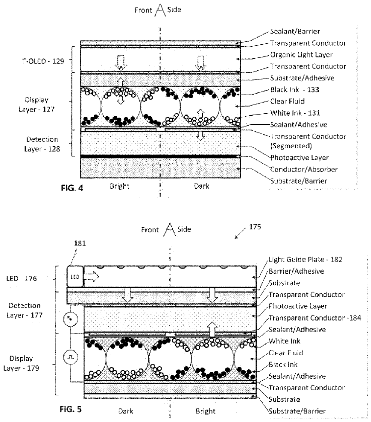
[0008]A verifiable display is provided that enables the visual content of the display to be detected and confirmed in a variety of ambient lighting conditions, environments, and operational states. In particular, the verifiable display has a display layer that is capable of visually setting an intended message for human or machine reading, with the intended message being set using pixels. Depending on the operational condition of the display and the ambient light, for example, the message that is actually displayed and perceivable may vary from the intended message. To detect what message is actually displayed, a light detection layer in the verifiable display detects the illumination state of the pixels, and in that way is able to detect what message is actually being presented by the display layer.
[0009]Advantageously, the verifiable display allows the automated and electronic detection of messages that were actually displayed, and with supporting circuitry and logic, may determine a level of perceptibility. With this information, decisions may be made regarding setting alarms, communicating warnings, or refreshing the intended message, for example. Further, an accurate electronic history of the actual messages may be saved for use in determining whether appropriate actions were taken responsive to the messages actually presented on the verifiable display.

Problems solved by technology

In another example, the processor may determine that the sensor has greatly exceeded the outer specification criteria, and cause an electro-optic indicator to show that the product is spoiled or otherwise unusable.
A particularly difficult problem occurs when an intended message has been sent to the display for the intelligent label, and then something occurs, either external or internal to the good or label, that makes the message imperceptible to the reader, which can be a human or a machine.
However, due to some problem, the intended message could not be communicated to the reader.
Today the condition of many of these goods is either unknown or if known, it is not immediately actionable by humans or systems where or when it matters most.
A big part of the problem is 1) the cost of evaluating the condition of the good, 2) the time it takes to extract the good from its normal distribution channel to test its quality, and 3) that the good is often times remote from the entity that most needs information about its quality.
Further, in some cases the destructive nature of existing methods of determining the condition of the goods makes testing to determine the good's condition economically unfeasible.

Method used


Image

  • Optically determining the condition of goods
  • Optically determining the condition of goods
  • Optically determining the condition of goods

Examples


example 1

[0234]It will be understood that the optical state monitor may be constructed for attaching to particular products or services. Often, the surfaces of a product for good to be monitored may be constructed in a different physical shape, or have different types of materials. Accordingly, the optical state monitor construction may be adjusted to adapt to the particular good or product that is intended to be monitored. For example, a good or product surface may have a flexible optical state monitor that is particularly useful for conforming to curved geometries. One such geometry is a tubular (or cylinder) form 1400 as illustrated in FIG. 45, in which the tubular optical state monitor 1401 is positioned inside the good 1402. The good may further be enclosed in a container 1403, which may be opaque or (semi-) transparent to allow ambient light to pass through. The optical state monitor 1401 may, for instance, be configured for reflection mode measurement of the good as shown (e.g., using...

example 2

[0236]For transmission mode detection of goods which are semi-transparent (translucent), it is advantageous to utilize an optical state monitor which provides controlled illumination internal to the monitor (as opposed to ambient light such as sunlight). FIG. 46 illustrates an optical state monitor with a “wrap-around” geometry 1500, in which the flexible optical state monitor 1501 is wrapped around a partial circumference of a cylindrically shaped good 1502. Again, the good may be contained in an at least semi-transparent and rigid container 1503. The circumferential extent of the optical state monitor is preferably at least such that the light source and monitor (detection) site are diametrically opposed (i.e., approximately half the circumference), in order to maximize the transmitted light 1507 towards to detector 1504. For the configuration shown in FIG. 46 it is particularly preferred to use a transmissive and flexible substrate which also functions as a light guide plate for ...

example 3

[0239]An alternative optical state monitor configuration for transmission mode detection of goods, which are semi-transparent (translucent), can be achieved by a wound geometry 1700 placed within the good 1701 as shown in FIG. 48. In this configuration the light detection layer 1706 receives light from one side and the light source layer 1703 emits light from the other side of the optical state monitor (both in the inward radial direction). Although there are many stack configurations possible, the light detection layer (e.g. of OPV or inorganic PV materials) could, for instance, be deposited (as shown in FIG. 48) on one side of a common opaque substrate 1704, with the light source layer (e.g., OLED based, or separate light guide substrate with LEDs) attached to the other side. The opaque property of the substrate 1704 enables that only light 1705 originating from the light source layer 1703 is detected by the part of the (segmented) light detection layer which located inside the wi...


PUM

PropertyMeasurementUnit
wavelengthsaaaaaaaaaa
timeaaaaaaaaaa
frequencyaaaaaaaaaa

Abstract

In one embodiment, an optical state monitor includes an a light source detection layer for detecting electromagnetic radiation from an associated good. The optical state monitor uses a processor to evaluate the detected radiation, and make a comparison to a pre-defined optical state profile for the good. By making this comparison, the optical state detector is able to determine a quality for the good. In a particular construction, the optical state detector has an integral light source, and the light detection layer is printed as s thin film device. In this way, a stand-alone self-contained sensor is constructed for determining the good's current quality.

Description

RELATED APPLICATIONS[0001]This application claims priority to U.S. provisional patent application No. 62 / 446,985, filed Jan. 17, 2017 and entitled “Disposable Spectrometer.” This application is also a continuation-in-part to U.S. patent application Ser. No. 15 / 368,622, filed Dec. 4, 2016, and entitled “Optically Determining Messages on a display,” which claims priority to U.S. provisional patent application No. 62 / 263,053, filed Dec. 4, 2015 and entitled “Optically Determining Messages on a Display;” to U.S. provisional patent application No. 62 / 341,768, filed May 26, 2016 and entitled “Systems and Methods for Independently Determining Visible Messages on Intelligent Visual Devices;” and to U.S. provisional patent application No. 62 / 365,108, filed Jul. 21, 2016 and entitled “Devices, Systems, and Methods for Optical Detection of Visual Displays;” all of which are incorporated herein by reference as if set for in their entirety. This application is also related to U.S. patent applica...

Claims


Application Information

Patent Timeline
Patent Type & Authority Patents(United States)
IPC IPC(8): G08B13/19G01N21/88G08B21/18
CPCG08B21/18G01N21/8806G01N2021/8835
Inventor ATKINSON, PAULRILUM, JOHNHUITEMA, EDZER
Owner CHROMERA
Learn More