Structure and apparatus for tire pressure monitoring

a technology of structure and apparatus, applied in the direction of elongated active element feed, resonance antenna, transportation and packaging, etc., can solve the problems of unstable and poor signal reception quality, battery to occupy space, unadjustable relative, etc., to prevent interference in the emitted wireless signal, save space, and stable signal reception quality

Active Publication Date: 2020-05-12
KEYCORE TECH CORP
View PDF1 Cites 2 Cited by
  • Summary
  • Abstract
  • Description
  • Claims
  • Application Information

AI Technical Summary

Benefits of technology

[0006]An objective of the present invention is to provide a structure and an apparatus for tire pressure monitoring, which prevent the interference in the emitted wireless signal and save space.
[0007]Another objective of the present invention is to provide a structure and an apparatus for tire pressure monitoring, which effectively achieve the effect of stable signal reception quality by means of the first circuit board and the second circuit board being disposed separately and vertically to each other and the power unit being stacked with the second circuit board of the second part.
[0008]Yet another objective of the present invention is to provide a structure and an apparatus for tire pressure monitoring, which effectively prevents the noise generation.
[0009]To achieve the above objectives, the present invention provides a structure for tire pressure monitoring, which comprises a main body, a signal processing unit, a sensing unit, and a power unit. The main body has a first part and a second part. The first part is disposed on a top side of the second part; the first part and the second part are not on the same plane. The signal processing unit is disposed at one side of the first part of the main body. The signal processing unit is provided with a wireless emitter, a processing unit connected to the wireless emitter, and a first circuit board. The wireless emitter and the processing unit are disposed on one side of the first circuit board. The sensing unit is disposed on the top side of the second part of the main body. The sensing unit is provided with at least one sensor and a second circuit board. The at least one sensor is disposed on one side of the second circuit board and connected to the processing unit disposed on the first circuit board. The power unit is disposed on a bottom side of the second part corresponding to the sensing unit; the power unit is connected to the signal processing unit and the sensing unit to provide power. By means of the design of the structure of the present invention, the interference in the emitted wireless signal can be prevented effectively and the occupied space can be saved.
[0010]The present invention also provides an apparatus for tire pressure monitoring, which comprises a case, a gas nozzle unit, and a structure for tire pressure monitoring. The case has a receiving space and a connecting part; the connecting part is disposed on an outside of the case. The gas nozzle unit has one end thereof movably connected to the connecting part. The structure for tire pressure monitoring which is disposed in the receiving space comprises a main body, a signal processing unit, a sensing unit, and a power unit. The main body has a first part and a second part. The first part is disposed on a top side of the second part; the first part and the second part are not on the same plane. The signal processing unit is disposed at one side of the first part of the main body. The signal processing unit is provided with a wireless emitter, a processing unit connected to the wireless emitter, and a first circuit board. The wireless emitter and the processing unit are disposed on one side of the first circuit board. The sensing unit is disposed on the top side of the second part of the main body. The sensing unit is provided with at least one sensor and a second circuit board. The at least one sensor is disposed on one side of the second circuit board and connected to the processing unit disposed on the first circuit board. The power unit is disposed on a bottom side of the second part corresponding to the sensing unit; the power unit is connected to the signal processing unit and the sensing unit to provide power. By means of the design of the apparatus of the present invention, the interference in the emitted wireless signal can be prevented effectively and the occupied space can be saved.

Problems solved by technology

Although the prior art apparatus for tire pressure monitoring is installed on the wheel frame of the car for monitoring the tire pressure, such a configuration causes another problem which is the emitting antenna and the tire sensor on the circuit board in the prior art apparatus are directional.
The emitting antenna and the tire sensor both disposed on the circuit board are on the same plane such that the installations of the tire sensor and the emitting antenna are specifically directional, which results in the problem of an unadjustable relative angle between the emitting antenna and the wheel frame due to the directionality of the tire sensor and further suffers from unstable and poor signal reception quality.
Also, because of the placements of the circuit board and the battery are on the same plane, the case requires more space to accommodate the battery, which causes the battery to occupy space.
To solve the problem of the battery occupation, other vendors stack the batteries on the back plate of the circuit board to save space; however, this configuration will cause the battery to interfere with the emitting antenna disposed on the front side of the circuit board to disturb the wireless signal sent by the emitting antenna.
As a result, the problems of poor wireless signal quality and unstable signal reception quality occur.
Due to different weights of the components (including the emitting antenna, the processing unit, the tire sensor, and the battery) and the centers of gravity of the components disposed on different positions on the same side of the circuit board, the disposition of the components on the circuit board causes imbalance such that the unbalanced weight of the apparatus for tire pressure monitoring occurs.
As a result, the noise problem caused during the operation of the apparatus for tire pressure monitoring installed on the wheel frame due to the unbalanced weight is generated.

Method used


Image

  • Structure and apparatus for tire pressure monitoring
  • Structure and apparatus for tire pressure monitoring
  • Structure and apparatus for tire pressure monitoring

Examples


Embodiment Construction

[0019]The above objectives of the present invention and the features of structure and function of the present invention are described according to preferred embodiments in accompanying figures.

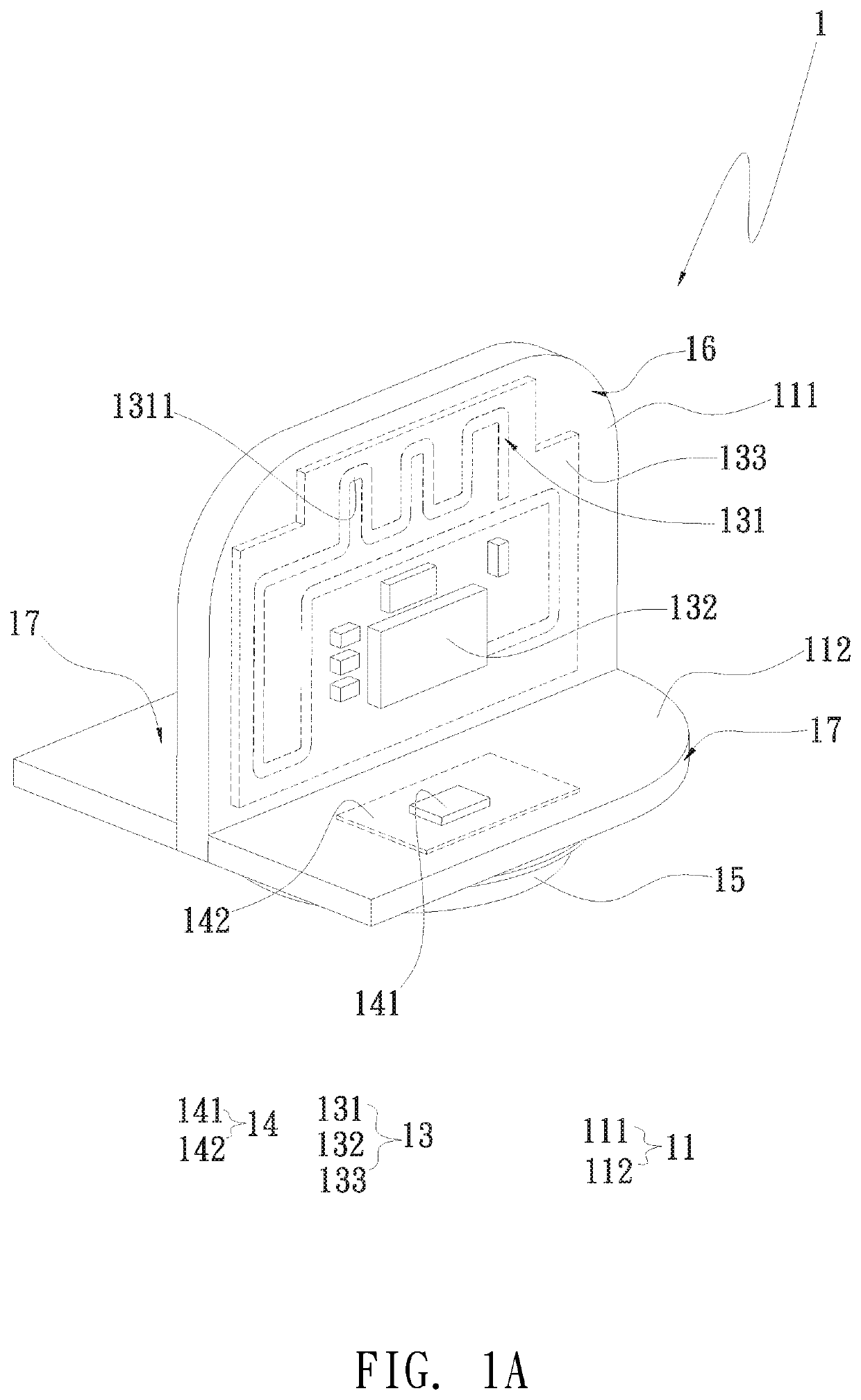
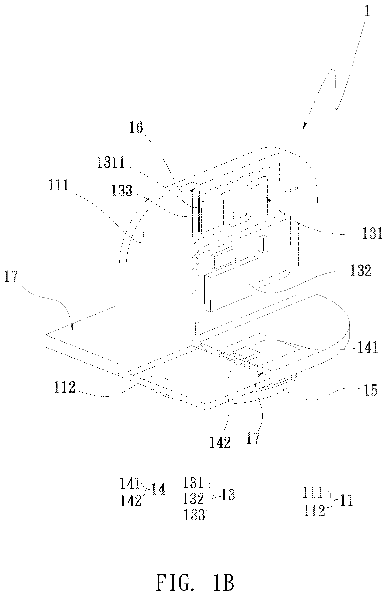
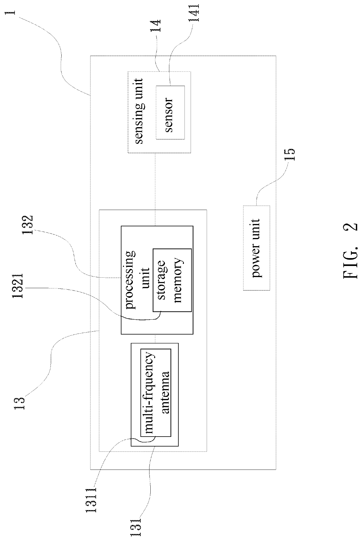
[0020]The present invention relates to a structure and an apparatus for tire pressure monitoring. Please refer to FIG. 1A which is a perspective assembled view of the structure for tire pressure monitoring according to an embodiment of the present invention, FIG. 1B which is a local perspective cross-sectional view of the structure for tire pressure monitoring according to an embodiment of the present invention, FIG. 2 which is a block diagram of the structure for tire pressure monitoring according to an embodiment of the present invention, FIG. 3 which is a perspective assembled view of the apparatus for tire pressure monitoring according to an embodiment of the present invention, FIG. 3A which is a perspective exploded view of the apparatus for tire pressure monitoring according to an embodi...


PUM


Abstract

An apparatus for tire pressure monitoring comprises a case, a gas nozzle unit movably connected to the outside of the case, and a structure for tire pressure monitoring which is received in a receiving space in the case. The structure for tire pressure monitoring comprises a main body, a signal processing unit, a sensing unit connected to the signal processing unit, and a power unit to provide power. The main body has a first part and a second part. The first part is disposed on a top side of the second part; the first and the second parts are not on the same plane. The signal processing unit and the sensing unit are disposed on one side of the first part and on the top side of the second part, respectively. The power unit is disposed on a bottom side of the second part.

Description

BACKGROUND OF THE INVENTIONField of the Invention[0001]The present invention relates to a structure and an apparatus for tire pressure monitoring and, in particular, to a structure and an apparatus for tire pressure monitoring, which can prevent the interference in the emitted wireless signal and save space.Description of Prior Art[0002]According to the statistical data, over 70 percent of the car accidents on the highway are caused by tire blowouts, but less than 10 percent of the drivers have the habit of checking the tire condition spontaneously. From the above data, abnormality of the car tire is always regarded as the most difficult issue that the drivers can prevent. Thus, the vendors develop an apparatus for tire pressure monitor to detect the tire condition constantly and remind the drivers to prevent the accident immediately when the abnormal tire condition occurs.[0003]As for the prior art apparatus for tire pressure monitoring which is installed on the wheel frame, it com...

Claims


Application Information

Patent Timeline
Patent Type & Authority Patents(United States)
IPC IPC(8): B60C23/04H01Q1/22
CPCB60C23/0452B60C23/0474B60C23/0464B60C23/041H01Q1/2241B60C23/0461B60C23/0444B60C23/0494H01Q9/42
Inventor CHIU, PO-WEILIN, WEI-CHENGTSENG, SHIH-HSIUHSIAO, CHIEN-JEN
Owner KEYCORE TECH CORP
Why Eureka
Try Eureka