Hybrid fluid circulation and signal transmission device

Active Publication Date: 2020-06-23
COVAL
View PDF5 Cites 4 Cited by
  • Summary
  • Abstract
  • Description
  • Claims
  • Application Information

AI Technical Summary

Problems solved by technology

In order to transfer signals between the above electronic pieces of equipment, the latter generally require a wire connection, which may be bulky, or a wireless connection which, if not bulky, may cause or be subjected to interferences.

Method used


Image

  • Hybrid fluid circulation and signal transmission device

Examples


Embodiment Construction

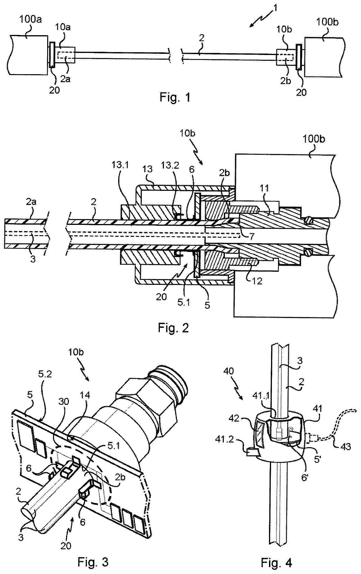
[0019]Referring to the appended drawings, the fluid circulation device 1 according to the invention includes a tube 2, preferably made of polyamide or polyurethane, having varying size and section. Such device is integrated in a fluid transportation circuit and can thus include several tubes and couplings associated therewith. It should be understood that, for simplicity and clarity in the description, the device is disclosed with only one tube dedicated to the transportation of air in a pneumatic circuit.

[0020]The fluid circulation device 1 further includes couplings 10a, 10b arranged in such a way as to allow a tight exchange of fluid between two units 100a, 100b of the fluid circuit, for instance pneumatic units (vacuum pumps, vent ducts, vacuum vessels, control valves, actuators, solenoid valves, sensors . . . ), via the tube 2. A first coupling 10a is thus tightly connected to a first fluid circulation unit 100a and to a first end 2a of the tube 2, and a second coupling 10b is ...


PUM

PropertyMeasurementUnit
conductiveaaaaaaaaaa
transmissionaaaaaaaaaa
electricallyaaaaaaaaaa

Abstract

A fluid circulation device having at least one fluid circulation tube, a first coupling sealingly coupled to a first end of the tube and a second coupling sealingly coupled to a second end of the tube in such a way as to allow the circulation of fluid between said two couplings via the tube. The device further has separate electronic elements. The tube has at least one conductor track extending along an outer surface of the tube. The track is suitable for transmitting at least one signal and arranged to engage with the abovementioned electronic elements.

Description

[0001]The invention relates to fluid circulation circuits and more particularly a fluid circulation tube provided with conductor tracks for transmitting signals between electronic means. Such signals may include data signals, power signals, bonding signals.TECHNICAL BACKGROUND OF THE INVENTION[0002]Fluid circulation devices using tubes for transporting fluid in many fields and for many different applications are known. Nowadays, fluid transportation circuits commonly include electronic equipment connected to an electric circuit to be powered and exchange data signals.[0003]In order to transfer signals between the above electronic pieces of equipment, the latter generally require a wire connection, which may be bulky, or a wireless connection which, if not bulky, may cause or be subjected to interferences.OBJECT OF THE INVENTION[0004]The object of the invention is to provide a hybrid solution for electrically connecting electric or electronic equipment integrated in a fluid transport...

Claims


Application Information

Patent Timeline
Patent Type & Authority Patents(United States)
IPC IPC(8): H01R13/00H01B7/18H01B7/00G01M3/40F16L33/22H01B7/28F16L11/127F16L25/01G08B7/06F16L9/12
CPCG01M3/40H01R13/005H01B7/1805F16L25/01F16L11/127H01B7/2813H01B7/0018F16L33/223G08B7/06F16L2201/30F16L9/125
Inventor MILHAU, PIERRECECCHIN, MICHEL
Owner COVAL
Why Eureka
Try Eureka