
System and methods for recreational sport heads-up display control

a display system and head-mounted technology, applied in the field of head-mounted heads-up display systems and a, can solve the problem of the obstacle of the hand-held nature of the head-mounted input devi

Active Publication Date: 2020-07-14
DISH NETWORK LLC
View PDF6 Cites 1 Cited by
  • Summary
  • Abstract
  • Description
  • Claims
  • Application Information

AI Technical Summary

Benefits of technology

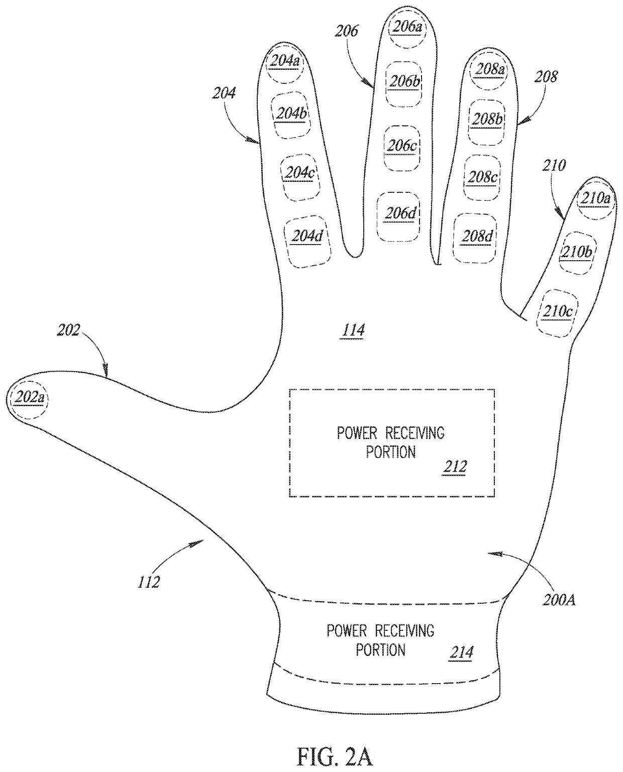
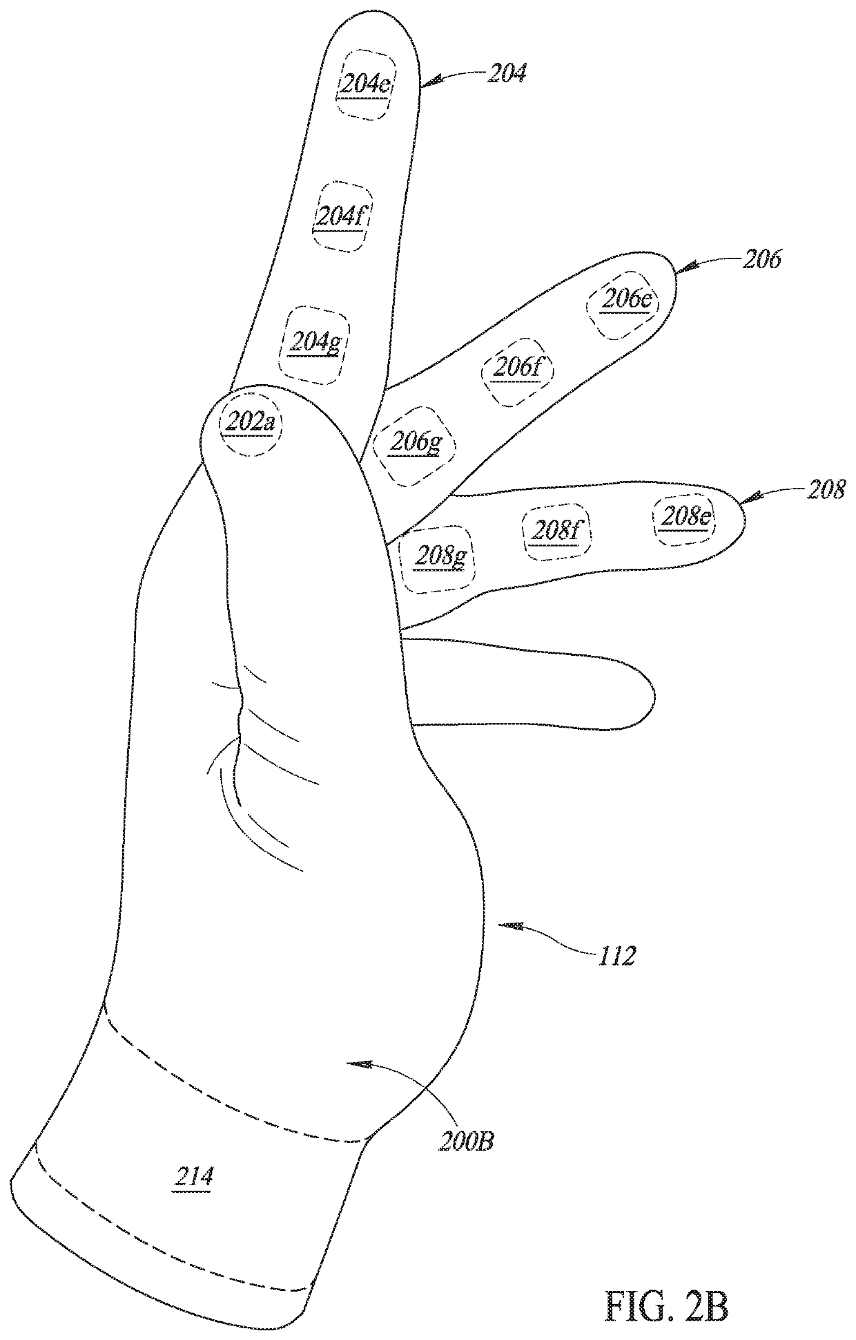
[0003]Embodiments disclosed herein are directed to heads-up display systems having a head-mounted heads-up display unit and a hand-worn input unit for controlling the heads-up display unit that is operable to control the head-mounted HUD. The hand-worn input unit has the shape of a glove or mitten, and includes a plurality of input elements provided on appendages thereof that are used to control the heads-up display unit. The input elements may include electronic components having electrical characteristics that change as a result of touch or pressure applied thereto. The hand-worn input unit transmits input signals to the heads-up display unit as a result of interactions involving the input elements, such as an interaction between a pair of the input elements. The heads-up display unit performs one or more operations based on the particular input signal received, which may include causing display of virtual image content. Advantageously, the hand-worn input unit allows a user to control the heads-up display unit without having to carry or access a separate hand-held controller. The hand-worn shape of the input unit provides an ergonomic device for providing user input that is intuitive and familiar.

Problems solved by technology

The hand-held nature of HUD input devices has been an obstacle to adoption in connection with athletic activities where a user's hands are engaged to participate in the activity.

Method used


Image

  • System and methods for recreational sport heads-up display control
  • System and methods for recreational sport heads-up display control
  • System and methods for recreational sport heads-up display control

Examples


Embodiment Construction

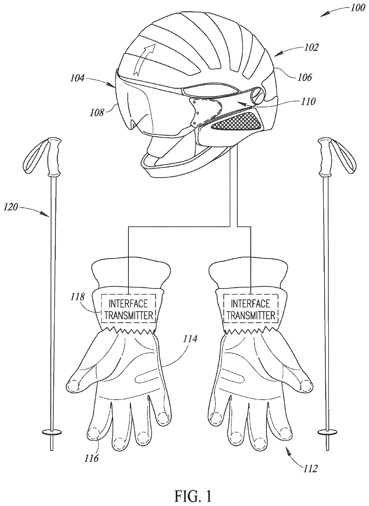
[0020]FIG. 1 shows an exterior of a head-mounted HUD system 100 for selectively displaying virtual imagery to a user according to one or more embodiments. The HUD system 100 includes a HUD unit 102 that is mountable to a head of a user for selectively displaying virtual visual content directly in the user's field of view. The HUD unit 102 of the current embodiment has a display 104 mounted on a helmet body 106 of the HUD unit 102. The display 104 has a transparent lens 108 through which a user can view scenery external to the HUD unit 102 and virtual image content provided by a virtual image display unit 110 of the HUD unit 102. The virtual image display unit 110 produces virtual image light that a user wearing the HUD unit 102 may view while also viewing scenery external to the HUD unit 102 at the same time. In one embodiment, the virtual image display unit 110 may produce image light that is projected onto a user's eye or onto the transparent lens 104 for viewing by the user. The ...


PUM


Abstract

Technologies are disclosed herein for controlling a head-mountable heads-up display system comprising a heads-up display unit and a hand cover. The hand cover includes a plurality of input elements located on appendages thereof that are configured to cause the hand cover to transmit input signals to the heads-up display unit. The heads-up display unit is configured to display virtual image content within a field of view of a user. As a result of receiving a user input, the heads-up display unit may display virtual image content based on a user input. The heads-up display unit updates the virtual image content as a result of receiving an input signal corresponding to an interaction between a pair of input elements of the hand cover. The heads-up display system may be useable in connection with a system of an outdoor recreational area to obtain information regarding the outdoor recreational area.

Description

BACKGROUNDTechnical Field[0001]The present disclosure relates to a head-mounted heads-up display system and a control method for a heads-up display device.Description of the Related Art[0002]Heads-up displays (HUDs) are devices provided with an electronic display that generates an image displayed within a user's normal field of view. HUDs have been used in a variety of applications from automobiles to airplanes in order to easily provide users with useful information. Some HUDs are provided as part of a head-mounted unit that can be worn on a user's head for overlaying information on top of or in the user's field of view. HUDs may have associated user input devices for controlling aspects of the image displayed, such as controlling the information content displayed. Previously, the user input devices of some HUDs have a joystick or pad for controlling a pointer or other selector in the image displayed. These user input devices are typically hand-held devices that occupy an entire ha...

Claims


Application Information

Patent Timeline
Patent Type & Authority Patents(United States)
IPC IPC(8): G06F3/01G09G5/00G06F3/0482H04L29/06G02B27/01A63C11/22G01C21/20
CPCG06F3/014H04L67/38A63C11/228G01C21/20G02B27/017G06F3/0482G09G5/006G09G2330/02G09G2370/04G09G2370/02G09G2354/00G02B2027/014G09G2370/16G06F3/147G06F3/011G06F3/03547G06F3/0346G02B2027/0138G02B2027/0187H04L67/131
Inventor BYERLEY, SETH
Owner DISH NETWORK LLC
Learn More