

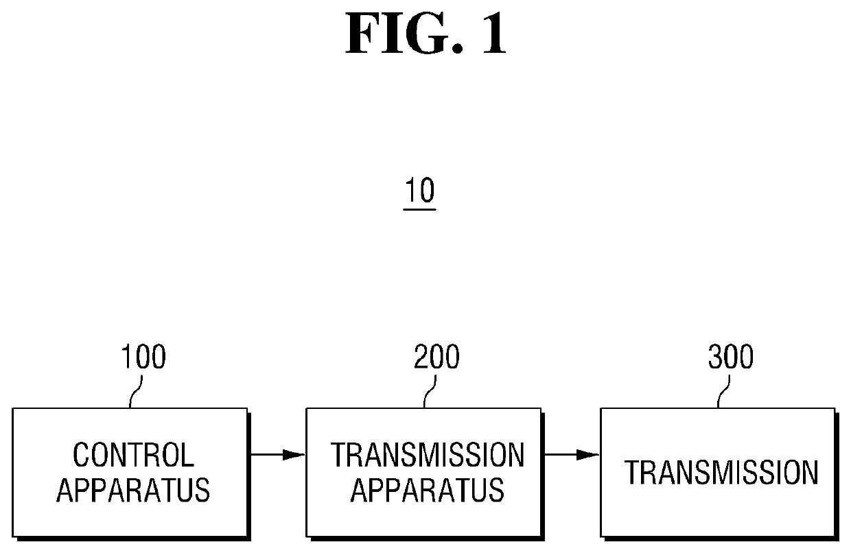
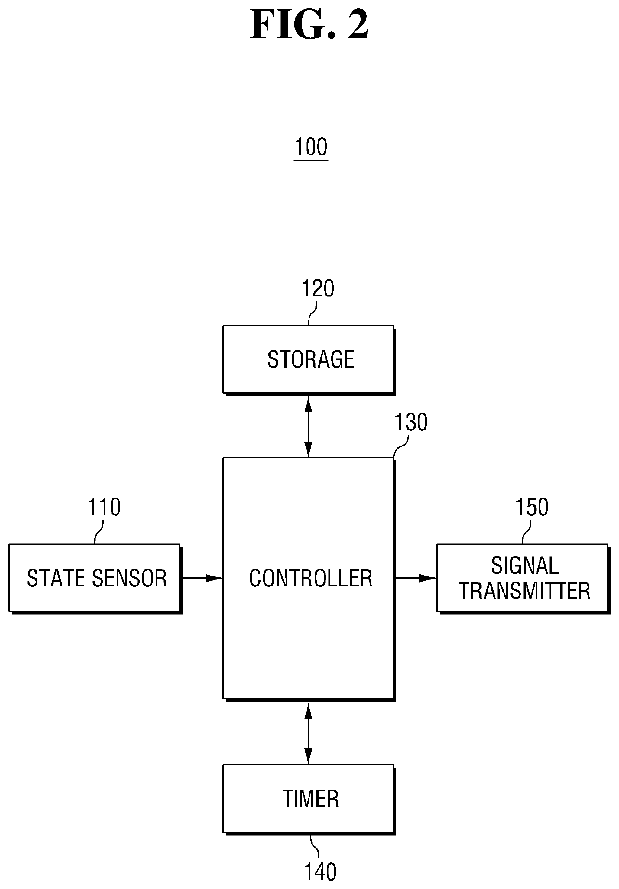
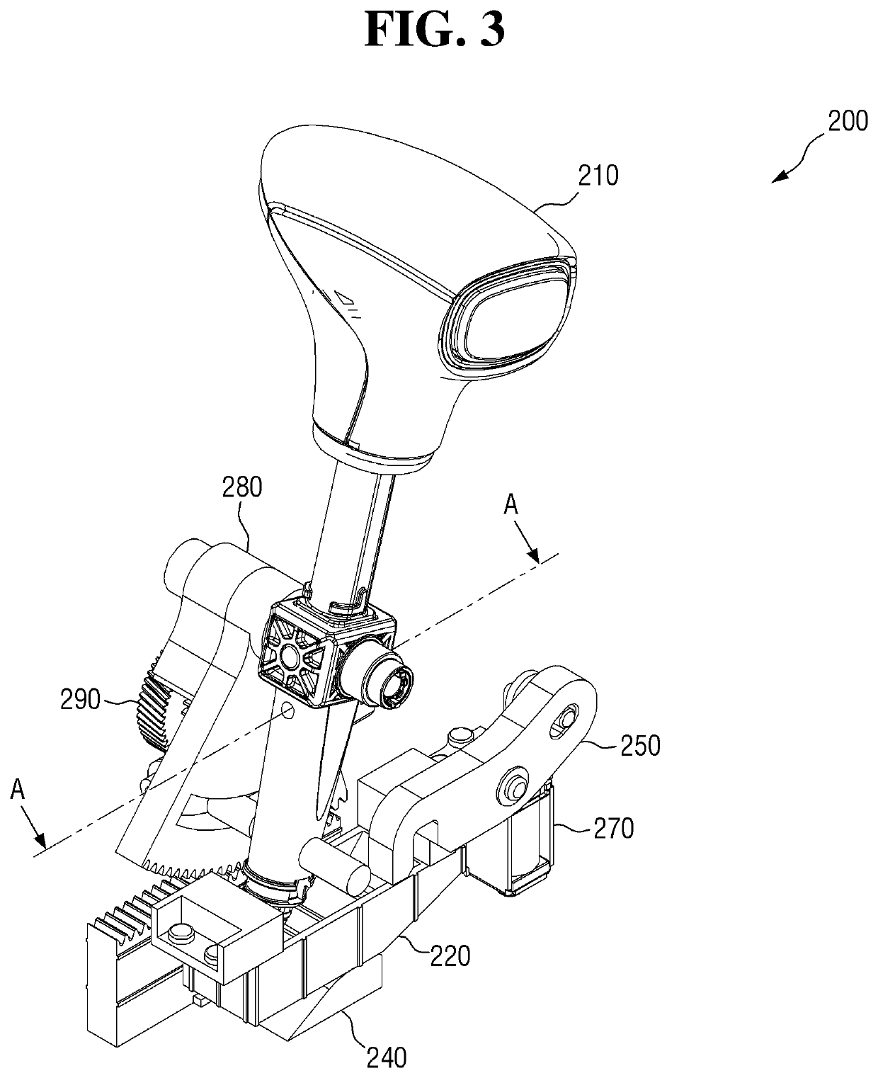
Transmission apparatus and transmission system
a transmission system and transmission apparatus technology, applied in the direction of friction gearings, gearing elements, gearing, etc., can solve the problems of increased accidents, gear stage not being shifted to the p stage,
- Summary
- Abstract
- Description
- Claims
- Application Information
AI Technical Summary
Benefits of technology
Problems solved by technology
Method used
Image

Examples
Embodiment Construction
[0037]Hereinafter, exemplary embodiments of the present disclosure will be described in detail with reference to the accompanying drawings. The advantages and features of the present disclosure and the manner of achieving the advantages and features will become apparent with reference to the embodiments described in detail below with the accompanying drawings. The present disclosure may, however, be implemented in many different forms and should not be construed as being limited to the embodiments set forth herein, and the embodiments are provided such that this disclosure will be thorough and complete and will fully convey the scope of the present disclosure to those skilled in the art, and the present disclosure is defined by only the scope of the appended claims. Same reference numerals refer to same components throughout the disclosure.
[0038]In some embodiments, well-known process steps, well-known structures and well-known techniques will not be specifically described in order ...
PUM
 Abstract
Description
Claims
Application Information