Method and device for providing a signal for a light control unit

a technology of light control unit and signal, which is applied in the direction of reradiation, television systems, instruments, etc., can solve the problems of blinding of the front-drive vehicle, other traffic participants may still be blinded, etc., and achieve the effect of reducing the computing expense of interval determination and easy and fast estimation

Active Publication Date: 2017-05-30
ROBERT BOSCH GMBH
View PDF20 Cites 3 Cited by
  • Summary
  • Abstract
  • Description
  • Claims
  • Application Information

AI Technical Summary

Benefits of technology

[0007]The present invention is based on the recognition that a camera-based distance determination has a system-caused error. This can be up to 15% of the determined distance. Therefore, it is advantageous to ensure the accuracy of a camera-based distance value using a camera-independent sensor, for example a radar sensor. In this way, a headlight range of headlights of a vehicle can be adjusted to a distance whose determination has been ensured, thus resulting in an improved illumination of the roadway in front of the vehicle without blinding other traffic participants.
[0011]In a further specific embodiment of the present invention, in the first determination step the interval can be determined based on a comparison of an angle between two light objects of a light object pair of the other vehicle with an expected angle, the angle being determined from a camera image. A light object pair can be understood for example as a pair of rear lights of a vehicle traveling in front, or two headlights of an oncoming vehicle. An angle between two light objects may be understood as an angle at a point of intersection between a first light beam at a first of the light objects and a second light beam at the second of the light objects. For example, the angle can be represented by an interval between a first pixel image of the first light object and a second pixel image of the second light object on an imaging plane of the camera. The point of intersection of the light beams can be located behind a focus plane of the camera. An expected angle may be understood as a stored expected value for the angle. For example, the expected angle can correspond to an interval of the light object from the vehicle and can be stored in a comparison table, and the allocated interval can be outputted when the relevant angle is determined. In this way, the spatial removal from the other vehicle can be estimated easily and quickly. No complicated object recognition is required for such a determination of the interval.
[0012]According to a further specific embodiment of the present invention, in the first determination step the interval can be determined based on a horizontal angle between the two light objects of the light object pair and based on an expected horizontal angle, the expected angle representing an averaged intermediate space between two vehicle lights. An averaged intermediate space between two vehicle lights may be understood as an average value, representative for a large number of different vehicles, of an intermediate space, where the intermediate space can be smaller than an upper boundary value and greater than a lower boundary value. The different vehicles can for example be members of a higher-order unified class of vehicles; thus, the different vehicles may have a class of common class features, such as for example a common outer dimension range. In this way, detection of light objects that are not part of the vehicle can be avoided, because the determination of the interval of the two light objects takes place via the horizontal angle, and it is not necessary to take into account an oblique position of the vehicle, so that the computing expense for the interval determination can be reduced.
[0013]In addition, in the first determination step a height angle to the other vehicle can be determined, and in the provision step the height angle can in addition be provided to the light control unit. The terrain in front of the vehicle can either reduce the headlight range, if there is an upward incline in front of the vehicle, or the terrain can increase the headlight range and thus result in blinding of a vehicle driving in front, if there is a downward incline in front of the vehicle. A height angle may be understood as an angle at a point of intersection between a horizontal plane and a beam to the light source. For example, an interval between a pixel image of the light source in a focus plane of the camera and a virtual horizon plane can represent the height angle. The virtual horizon plane can for example be provided by an artificial horizon, or may be a stored horizon plane at an initialization state. Through provision of the height angle, an upper light-dark cutoff of a headlight cone can be adapted to a roadway contour. If the other vehicle is situated above or below the vehicle, the upper light-dark cutoff can be adapted upward or downward.
[0016]In addition, according to a further specific embodiment, in the first determination step at least one horizontal direction to the other vehicle can additionally be determined, and in the second determination step the distance from the vehicle traveling in front can in addition be determined using at least the horizontal direction. For example, the horizontal direction can be determined relative to a mid-axis of the vehicle. Through the use of the horizontal direction in the second determination step, the camera-independent sensor can send out the energy in focused form in the direction toward the other vehicle. In this way, a high energy density can be achieved at the other vehicle, and a strong echo can come back to the camera-independent sensor. In addition, the interpretation of wrongly received echoes as a useful signal can be avoided, because a directed reception of the echo is carried out, so that reception of radar echoes is possible only from a particular direction.

Problems solved by technology

If an overly large vertical angle to the light of the other traffic participant is determined, and the headlight range of the headlight is set such that an upper light-dark cutoff runs below the light of the other traffic participant, the other traffic participant may nonetheless be blinded.
The terrain in front of the vehicle can either reduce the headlight range, if there is an upward incline in front of the vehicle, or the terrain can increase the headlight range and thus result in blinding of a vehicle driving in front, if there is a downward incline in front of the vehicle.

Method used


Image

  • Method and device for providing a signal for a light control unit
  • Method and device for providing a signal for a light control unit
  • Method and device for providing a signal for a light control unit

Examples


Embodiment Construction

[0023]In the following description of preferred exemplary embodiments of the present invention, identical or similar reference characters are used for elements shown in the various Figures and having similar functions, so that repeated description of these elements is omitted.

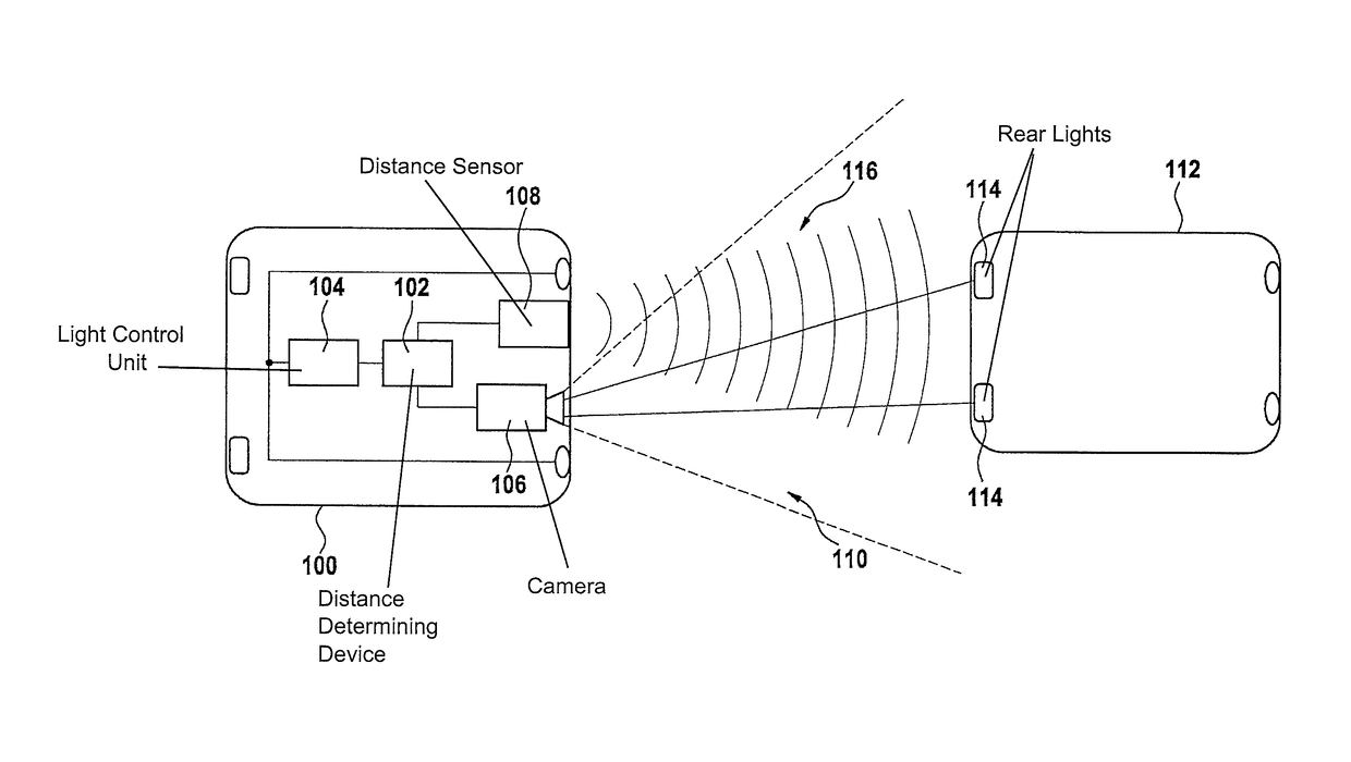
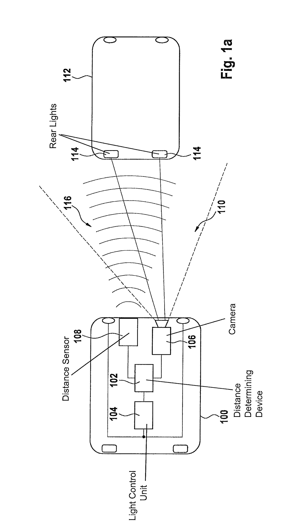
[0024]FIG. 1a shows a representation of a vehicle 100 having a device 102 for providing a signal to a light control unit 104 according to an exemplary embodiment of the present invention. Vehicle 100 has a camera 106 and a camera-independent distance sensor 108. A vehicle in front 112 is situated in an acquisition region 110 of camera 106. Two rear lights 114 of vehicle in front 112 are situated at a distance from one another. From a point of view of camera 106, rear lights 114 of vehicle in front 112 have a measurable angle to one another. In an imaging plane of camera 106, image points representing rear lights 114 have a smaller interval from one another. The larger the reduced interval in the imaging plane o...


PUM


Abstract

A method for providing a signal to a light control unit of at least one headlight of a vehicle that has a camera for acquiring a surrounding environment of a vehicle, the method including a step of determination of an interval between the vehicle and another vehicle using the camera. The method further includes a step of determination of a distance between the vehicle and the other vehicle using a camera-independent sensor. In addition, the method includes a step of plausibilization of the interval using the distance, the interval being plausibilized if a difference between the interval and the distance is smaller than a tolerance value. Finally, the method includes a step of provision the interval via an interface to a light control unit of the headlight.

Description

FIELD OF THE INVENTION[0001]The present invention relates to a method for providing a signal for a light control unit, to a device for providing a signal for light control unit, and to a corresponding computer program product.BACKGROUND INFORMATION[0002]In order to avoid blinding other traffic participants, it is important to determine the distance from a vehicle traveling in front.[0003]German Patent No. 43 36 288 describes a device for monitoring the rear or front space of a parking motor vehicle using a video camera having an image sharpness control that can follow an object, once recognized, with sharpness over the entire search field, using autofocus.[0004]The device uses this property for an image-processing-supported tracking of the viewing angle of a video camera that is pivotable and can be inclined, whereby an object limiting the rear-side or front-side penetration depth of the vehicle can be viewed up until contact with the bumper.SUMMARY[0005]Against this background, the...

Claims


Application Information

Patent Timeline
Patent Type & Authority Patents(United States)
IPC IPC(8): B60Q1/08G01S13/00B60Q1/14H04N7/18G01S13/86B60Q1/04
CPCH04N7/183B60Q1/143G01S13/867B60Q2300/056B60Q2300/41B60Q2300/42B60W2550/308B60W2554/801
Inventor FABER, PETKOSCHWARZENBERG, GREGOR
Owner ROBERT BOSCH GMBH
Why Eureka
Try Eureka