
Test piece and manufacturing method thereof

a technology of test pieces and manufacturing methods, applied in the field of test pieces, can solve the problems of reducing the accuracy of measuring values, increasing resistance, and reducing conductivity, and achieves excellent uniformity of film, stable test current, and low resistance

Inactive Publication Date: 2015-04-21
CHIANG HUI PING +2
View PDF2 Cites 0 Cited by
  • Summary
  • Abstract
  • Description
  • Claims
  • Application Information

AI Technical Summary

Benefits of technology

[0009]The technical characteristics of the present invention are that forming the first metal pattern layer and the second metal pattern layer by vacuum coating, therefore, the excellent uniformity of film is obtained, for example, the average error is less than 300Å. In addition, the test piece has low resistance, so as to provide a stable test current to prevent the interpretation mistakes and to improve the test efficiency.

Problems solved by technology

Nowadays, the pattern of the reference electrode or the working electrode is pasted on the insulating substrate; however, the adhesive will increase the resistance and decrease the conductivity.
The precision of the measuring values would be decreased and the interpretation may be wrong due to those disadvantages.
However, there are still many processing steps after electroplating, such as etching, so that the electrode pattern is easily peeled.

Method used

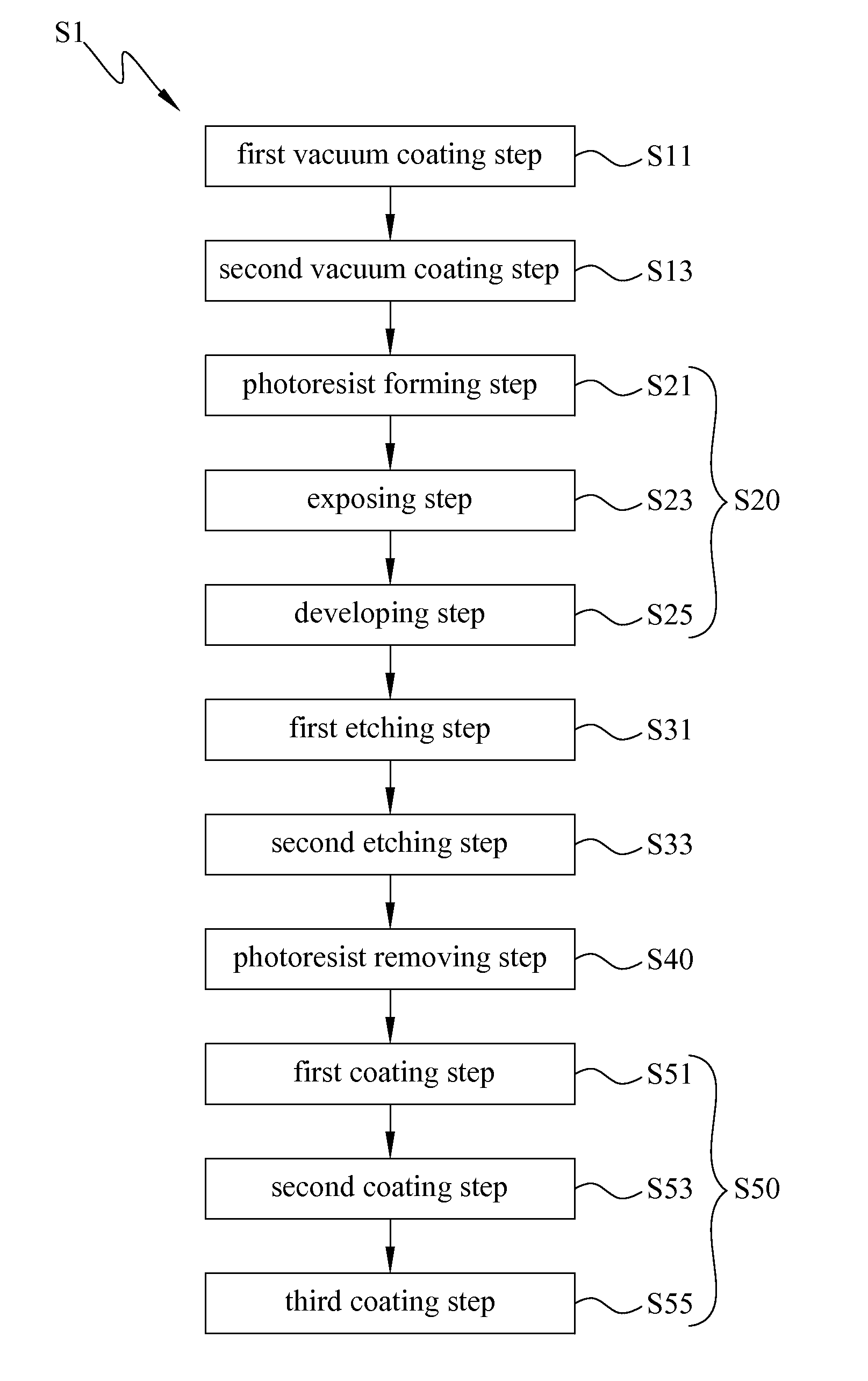
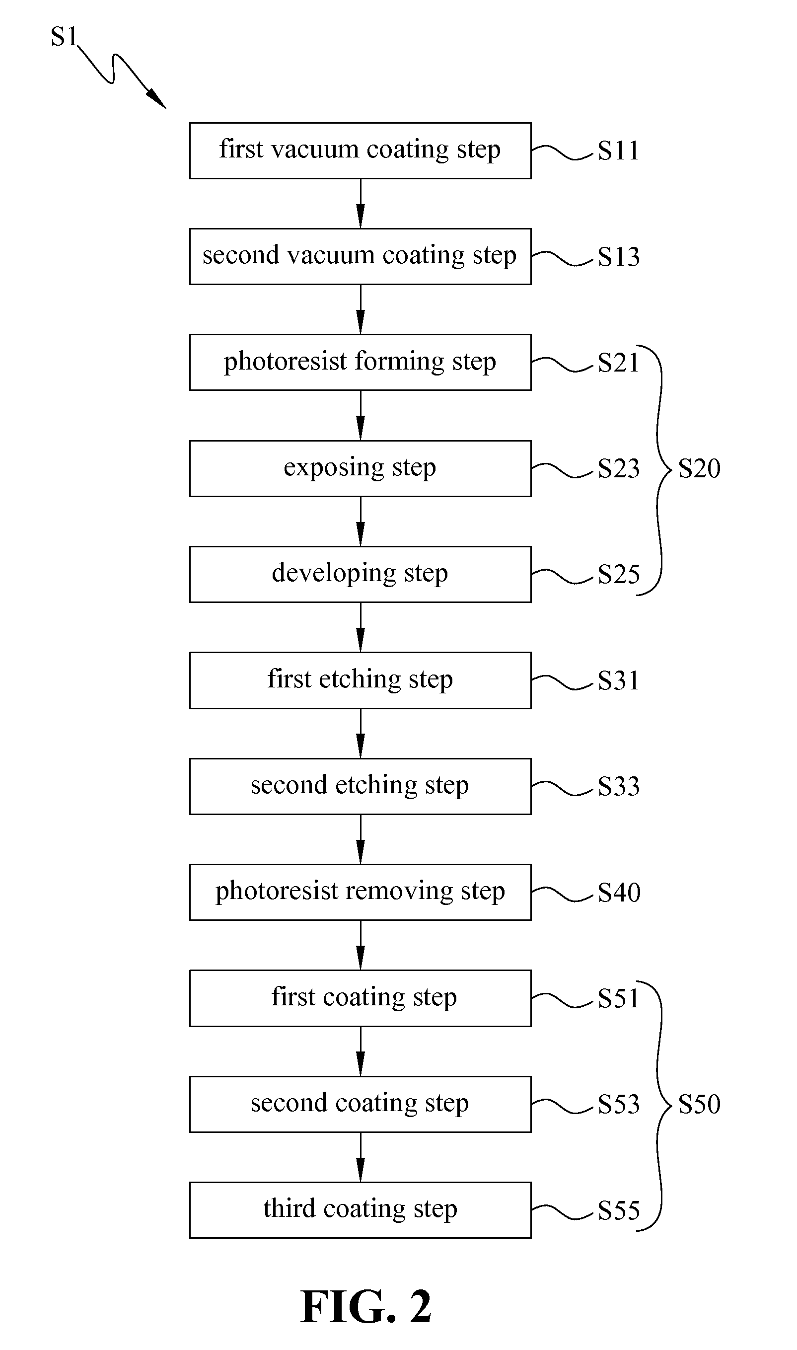

Image

  • Test piece and manufacturing method thereof
  • Test piece and manufacturing method thereof
  • Test piece and manufacturing method thereof

Examples


Embodiment Construction

[0014]The present invention may be embodied in various forms and the details of the preferred embodiments of the present invention will be described in the subsequent content with reference to the accompanying drawings. Modifications of the shape of the present invention shall too be considered to be within the spirit of the present invention.

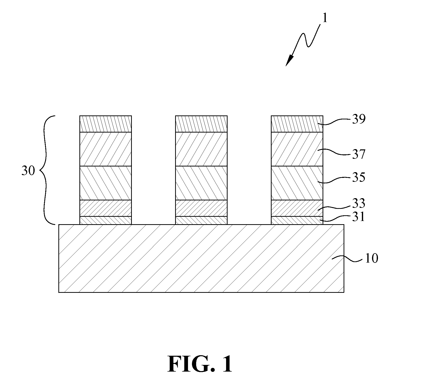
[0015]FIG. 1 is a schematic drawing for illustrating a test piece of the present invention. As shown in FIG. 1, the test piece 1 of the present invention includes to an insulating substrate 10, and a circuit pattern structure 30 formed on the insulating substrate 10, wherein circuit pattern structure 30 includes a first metal pattern layer 31, a second metal pattern layer 33, a third metal pattern layer 35, a fourth metal pattern layer 37, and a fifth metal pattern layer 39 laminated from bottom to up in sequence. The first metal pattern layer 31, the second metal pattern layer 33, the third metal pattern layer 35, the fourth metal pattern laye...


PUM

PropertyMeasurementUnit
thicknessaaaaaaaaaa
thicknessaaaaaaaaaa
thicknessaaaaaaaaaa

Abstract

Disclosed are a test piece and the manufacturing method thereof The test piece includes an insulating substrate and a circuit pattern structure formed on the insulating substrate, wherein circuit pattern structure includes a first metal pattern layer, a second metal pattern layer, a third metal pattern layer, a fourth metal pattern layer, and a fifth metal pattern layer. The first metal pattern layer, the second metal pattern layer, the third metal pattern layer, the fourth metal pattern layer, and the fifth metal pattern layer have same pattern shapes and positions thereof are overlapping in a plane. The first metal pattern layer and the second metal pattern layer are nano-metal films formed by vacuum coating, therefore, the test piece has excellent uniformity of film and low resistance to provide a stable test current to prevent the judging mistakes and to improve the test efficiency.

Description

CROSS-REFERENCES TO RELATED APPLICATIONS[0001]This application claims the priority of Taiwanese patent application No. 101108907, filed on Mar. 15, 2012, which is incorporated herewith by reference.BACKGROUND OF THE INVENTION[0002]1. Field of the Invention[0003]The present invention generally relates to a test piece, more specifically to a test piece for measuring blood glucose, and the test piece includes at least one nano metal pattern layer.[0004]2. The Prior Arts[0005]Chemical test pieces have already broadly applied in fluidic inspection and testing in decades. Well-known chemical test pieces include a reference electrode and a working electrode, and the manufacturing method and material of electrodes affect the precision of the measuring value. For example, the lower of the resistance of the conductive parts of the chemical test pieces, the better conductive stability is obtained.[0006]Nowadays, the pattern of the reference electrode or the working electrode is pasted on the i...

Claims


Application Information

Patent Timeline
Patent Type & Authority Patents(United States)
IPC IPC(8): H01L21/302H01L21/461C23F1/16C23F1/18C23F1/20G01N33/52G01N33/66H01L21/3213H05K1/09H05K1/16H05K3/38
CPCG01N33/66C23F1/16C23F1/18H01L21/32134C23F1/20G01N33/525H05K1/09H05K1/16H05K3/388H05K2201/0338H05K2203/1476
Inventor LIN, YU-LIN
Owner CHIANG HUI PING
Learn More