Earth working machine whose working apparatus is displaceable out of its operating position using an onboard actuator

a technology of working apparatus and actuator, which is applied in the field of earth working machines to achieve the effect of avoiding or reducing the installation moment load

Active Publication Date: 2020-07-28
WIRTGEN GMBH
View PDF14 Cites 4 Cited by
  • Summary
  • Abstract
  • Description
  • Claims
  • Application Information

AI Technical Summary

Benefits of technology

[0010]The object of the present invention is to refine an earth working machine of the kind recited initially in such a way that upon a replacement of the working apparatus on the working machine, the working apparatus can be displaced as simply and quickly as possible out of the operating position while avoiding or at least reducing an installation moment load on the drive configuration.

Problems solved by technology

In the case of the positioning cylinder arranged remotely from the non-locating bearing, large installation moments unavoidably act at least on the bearing subassemblies involved during both deinstallation and installation of the milling drum, since a considerable load arm exists between the hydraulic positioning cylinder and the bearing components to be displaced by it.
The solution known from U.S. Pat. No. 4,704,045 A has the disadvantage that the hydraulic positioning cylinders that move the side frames must exert an axial force on the milling drum during the entire operation of the known earth milling machine in order to hold the drum in an axially clamped state.

Method used


Image

  • Earth working machine whose working apparatus is displaceable out of its operating position using an onboard actuator
  • Earth working machine whose working apparatus is displaceable out of its operating position using an onboard actuator
  • Earth working machine whose working apparatus is displaceable out of its operating position using an onboard actuator

Examples


first embodiment

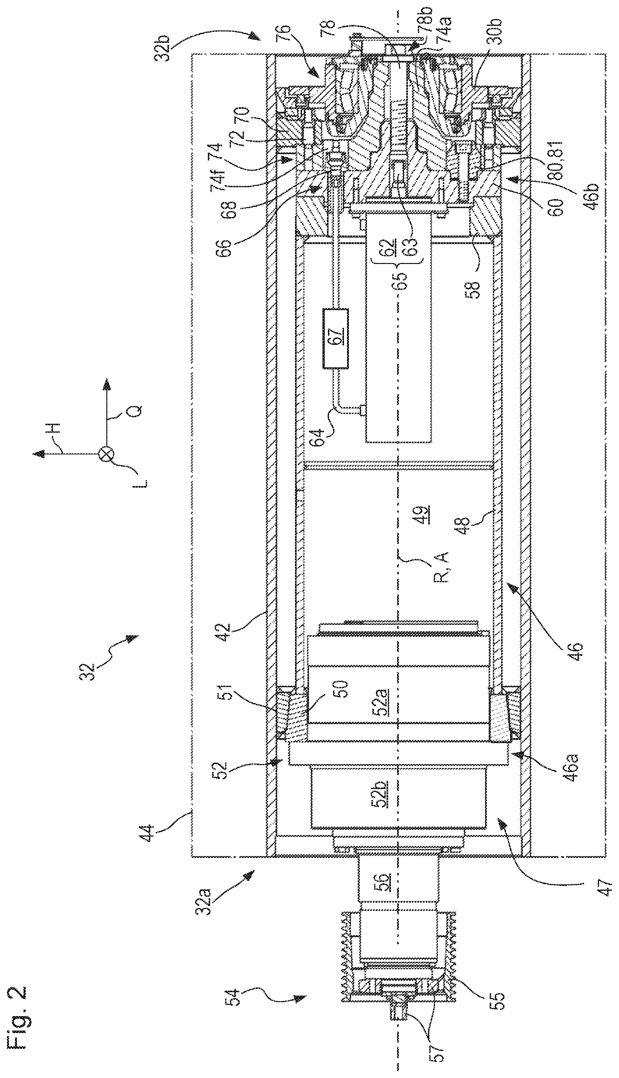
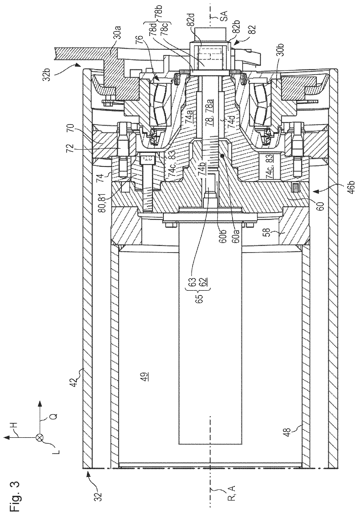
[0141]The first embodiment already explained in FIGS. 2 and 3 will be explained below in terms of operation thereof for deinstalling and installing milling drum 32 from and onto drive configuration 46 using actuator 65.

[0142]In the variant embodiment of FIGS. 4 to 6, coupling configuration 68′ is embodied directly on cover 60. Energy connector line 64 passes through coupling configuration 68′ so that hydraulic cylinder 62 can be supplied with hydraulic fluid.

[0143]The point at which energy connector line 64 connects to hydraulic cylinder 62 is selected merely by way of example. Be it noted that all the hydraulic cylinders depicted in the Figures are double-acting cylinders. Each of two hydraulic chambers, acting in opposite directions, of a hydraulic cylinder that is depicted is coupled to a respective energy connector line 64. For the sake of clarity, and because it is sufficient for a basic understanding of the embodiment, in many depictions only one of two energy connector lines ...

second embodiment

[0159]FIG. 8 shows the drive configuration and milling drum (working apparatus).

[0160]Components and component portions identical and functionally identical to those in the first embodiment are labeled in the second embodiment with the same reference characters but incremented by 100. The second embodiment of FIG. 8 is explained below only insofar as it differs from the first embodiment to an extent essential in terms of the invention.

[0161]A first essential modification of the second embodiment as compared with the previously described first embodiment is the conformation of centering stem 160a, which both acts as a centering configuration with respect to connecting flange 174 of milling drum 132 and serves as a bearing stem with respect to non-locating bearing 176.

[0162]Counterpart centering configuration 174b is thus once again embodied as a recess. In contrast to the first embodiment, in the second exemplifying embodiment centering stem 160a not only projects axially into connec...

third embodiment

[0179]Lastly, FIG. 12 depicts a third embodiment that is intended to show that central retaining bolt 278 can also be bolted to piston rod 263 of hydraulic cylinder 262 for axial positional retention of milling drum 32 on drive configuration 46.

[0180]Components and component portions identical and functionally identical to those of the first embodiment are labeled in the third embodiment with the same reference characters but incremented by 200. The third embodiment of FIG. 12 will be explained here only insofar as it differs from the first embodiment to an extent essential in terms of the invention.

[0181]The third embodiment depicted in FIG. 12, having retaining bolt 278 screwed into piston rod 263, is of course also applicable to the design of the second embodiment in which the centering stem and the bearing stem are implemented in a single component. All that is then necessary is for bolt head 278b to brace against an auxiliary component that transfers force from bolt head 278b o...


PUM


Abstract

An earth working machine (10) includes a machine body (13) having a machine frame (12) and a drive configuration (46), rotationally drivable relative to the machine frame (12), and to which configuration a working apparatus (32) embodied for earth working is releasably connected in torque-transferring fashion, in an operating position, for rotation together around a drive axis (A), such that when the connection is released, the working apparatus (32) is removable from the operating position in an axial direction relative to the drive configuration (46) for deinstallation from the drive configuration (46) and, for installation on the drive configuration (46), is conveyable into the operating position in an axial direction relative to the drive configuration (46), an actuator (65) being provided which is embodied to move the working apparatus (32) out of the operating position when the connection is released.

Description

BACKGROUND OF THE INVENTION[0001]The present invention relates to an earth working machine, such as a road milling machine, recycler, stabilizer, or surface miner, encompassing a machine body having a machine frame and a drive configuration, rotationally drivable relative to the machine frame around a drive axis that defines an axial direction, that extends along the drive rotation axis from an introduction longitudinal end at which the drive configuration is embodied for introduction of a drive torque to a functional longitudinal end located axially oppositely from the introduction longitudinal end, and to which configuration a working apparatus embodied for earth working is releasably connected in torque-transferring fashion, in an operating position operational for earth working, for rotation together around the drive axis, such that when the connection is released, the working apparatus is removable from the operating position in an axial direction relative to the drive configur...

Claims


Application Information

Patent Timeline
Patent Type & Authority Patents(United States)
IPC IPC(8): E01C23/08E01C23/12B23C1/00B23C1/02B23Q1/28E01C23/088B23C1/027
CPCE01C23/127E01C23/088B23C1/027B23C1/007B23Q1/28E01C21/00E21C47/00
Inventor BERNING, CHRISTIANBUHR, KARSTENFRANKEMÖLLE, MARKUSLEHNERT, THOMASSALZ, ANDREASWILHELMI, HARDY
Owner WIRTGEN GMBH
Why Eureka
Try Eureka