Rear subframe structure

a subframe and rear frame technology, applied in the field of rear subframe structure of vehicles, can solve the problems of high rigidity, lack of a closed section of a rear cross member, and insufficient disclosure of a stabilizer and a stabilizer support member in patent literature, so as to achieve the effect of not increasing the number of parts

Active Publication Date: 2020-08-18
MAZDA MOTOR CORP
View PDF20 Cites 4 Cited by
  • Summary
  • Abstract
  • Description
  • Claims
  • Application Information

AI Technical Summary

Benefits of technology

[0009]An object of the present invention is to provide a rear subframe structure which enables to increase a closed section of a rear cross member, while securing a space for installing a stabilizer without increasing the number of parts.

Problems solved by technology

However, simply increasing a closed section of a rear cross member may make it difficult to secure high rigidity, while securing a space for installing a stabilizer.
However, Patent Literature fails to disclose a stabilizer and a stabilizer support member.
However, Patent Literature 2 lacks a technical idea that a closed section of a rear cross member is increased.

Method used


Image

  • Rear subframe structure
  • Rear subframe structure
  • Rear subframe structure

Examples


Embodiment Construction

[0027]In the following, an embodiment of the present invention is described in detail based on the drawings.

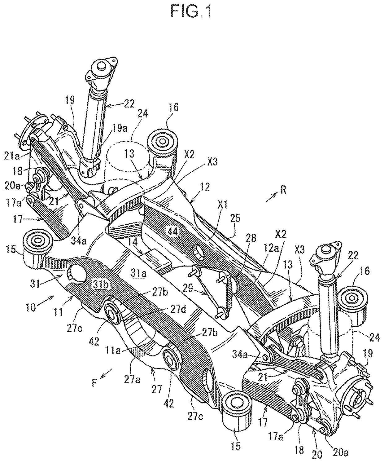
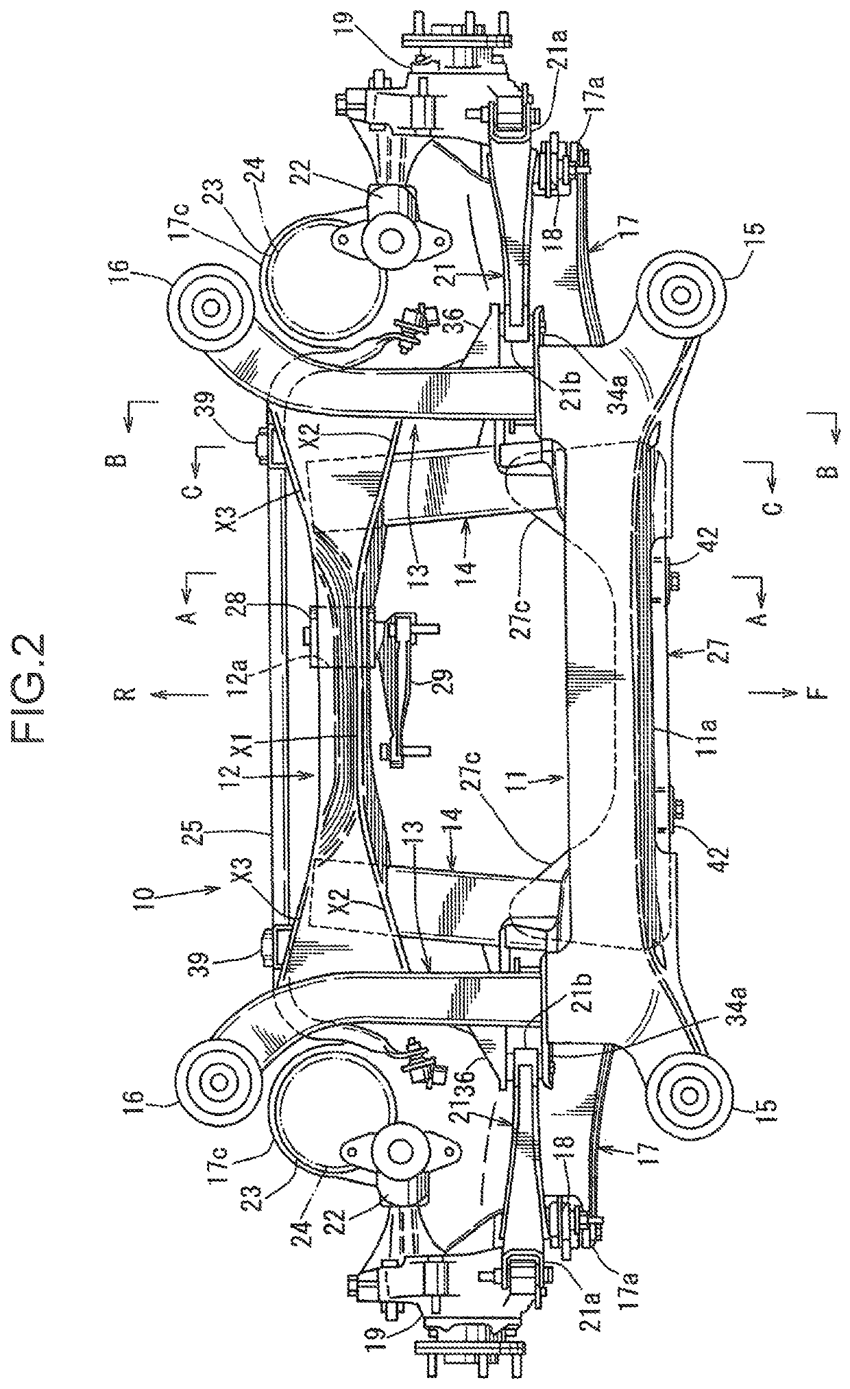
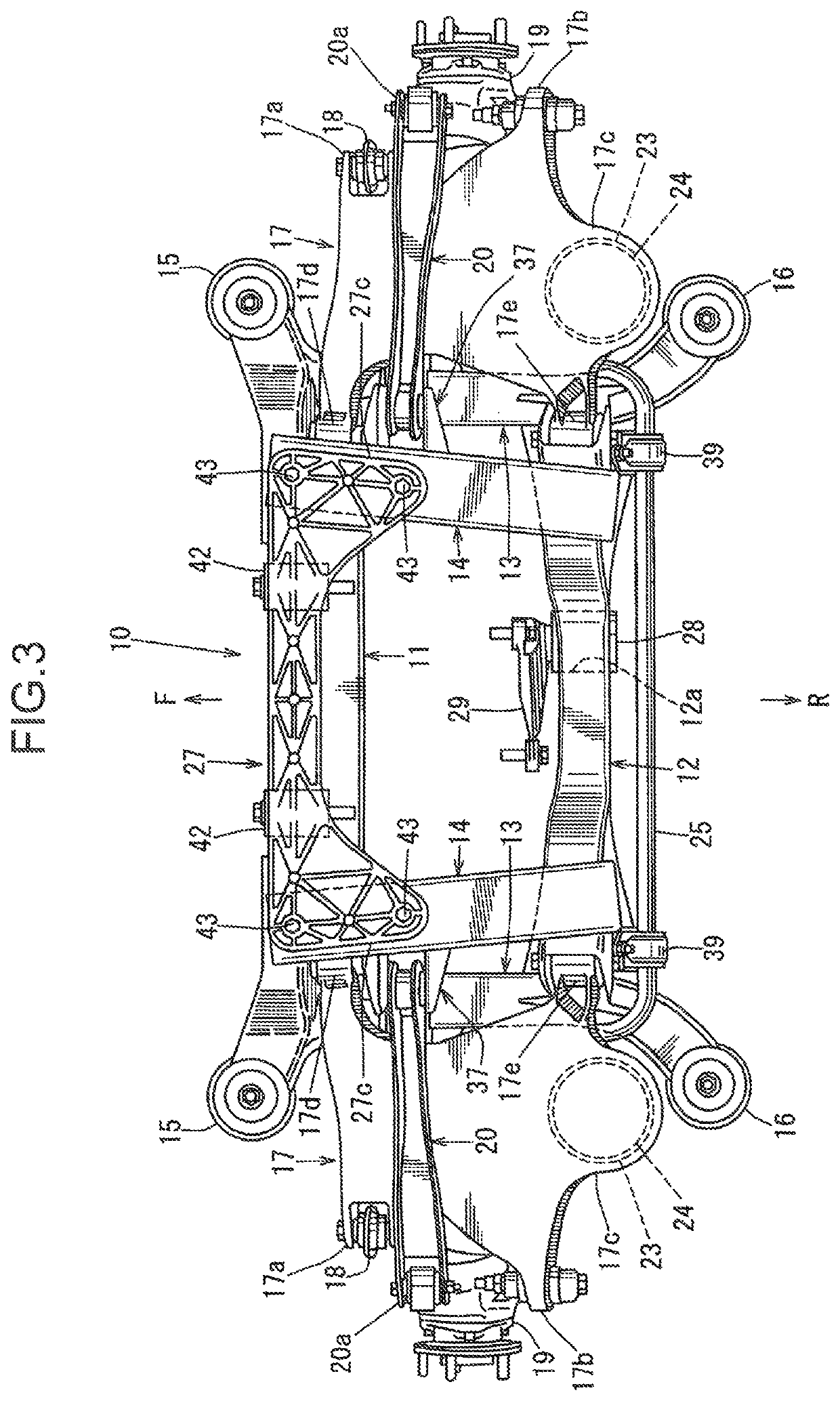
[0028]FIG. 1 is a perspective view of a rear subframe structure, FIG. 2 is a plan view of the rear subframe structure, FIG. 3 is a bottom view of the rear subframe structure, FIG. 4 is a front view of the rear subframe structure, and FIG. 5 is a rear view of the rear subframe structure. In FIG. 1, the arrow F indicates a vehicle front side, the arrow R indicates a vehicle rear side, the arrow IN indicates an inner side in a vehicle width direction, and the arrow OUT indicates an outer side in a vehicle width direction (the same definition is also applied to the other drawings).

[0029]Referring to FIG. 1 to FIG. 5, a rear subframe 10 for supporting a rear suspension includes a front cross member 11 extending in the vehicle width direction on the front side, a rear cross member 12 extending in the vehicle width direction on the rear side, a pair of upper side members 13 and 13 (h...


PUM


Abstract

A rear subframe structure is provided with a rear subframe configured such that a front cross member, a rear cross member, a pair of left and right upper side members extending in a vehicle front-rear direction, and a pair of left and right lower side members extending in the vehicle front-rear direction are connected; and a vehicle-body mounting portion formed on each of both ends of the front cross member in the vehicle width direction, and on each of rear ends of the upper side members. The rear subframe further includes a lower-arm support portion formed on a lower lateral portion of the rear cross member, and a stabilizer support member for supporting a stabilizer. The rear cross member connects the upper side members and the lower side members in an up-down direction. The rear cross member includes an upper-surface rear-side projection portion projecting rearwardly. The stabilizer support member is mounted between the lower-arm support portion and the upper-surface rear-side projection portion of the rear cross member.

Description

TECHNICAL FIELD[0001]The present invention relates to a rear subframe structure of a vehicle, and more particularly, to a rear subframe structure provided with a rear subframe configured such that a front cross member extending in a vehicle width direction, a rear cross member extending in the vehicle width direction on the rear side of the front cross member, a pair of left and right upper side members extending in a vehicle front-rear direction, and a pair of left and right lower side members extending in the vehicle front-rear direction are connected in a substantially grid pattern in a plan view of a vehicle; and a vehicle-body mounting portion formed on each of both ends of the front cross member in the vehicle width direction, and on each of rear ends of the upper side members.BACKGROUND ART[0002]Generally, a rear subframe is configured such that a pair of front and rear cross members extending in a vehicle width direction, and left and right side members extending in a vehicl...

Claims


Application Information

Patent Timeline
Patent Type & Authority Patents(United States)
IPC IPC(8): B62D21/03B62D21/11
CPCB62D21/11B62D21/03B60G2200/144B60G2204/15B60G2206/604B60G2206/60
Inventor TANAKA, MASAAKIKOMIYA, KATSUYUKI
Owner MAZDA MOTOR CORP
Why Eureka
Try Eureka