Attachment structure for solenoid valve to carburetor unit

a technology for carburetor units and solenoid valves, which is applied in the direction of carburettors, machines/engines, and feeding systems, etc., can solve the problems of difficult to secure the solenoid valve b>2, > in a stable condition, > and can come loose, so as to prevent slipping out and improve manufacturing efficiency.

Active Publication Date: 2016-12-08
ZAMA JAPAN
View PDF0 Cites 0 Cited by
  • Summary
  • Abstract
  • Description
  • Claims
  • Application Information

AI Technical Summary

Benefits of technology

[0010]Furthermore, in the present invention, at least one of the engaging portion or the rod-like supporting portion is formed from a suitably elastic hard material, and can therefore serve for elastic engagement.
[0011]Furthermore, in the present invention the groove-like engagement portion of the engaging portion is formed substantially perpendicularly to the axial line direction of the cover, i.e., substantially perpendicular to the direction in which the solenoid valve is inserted into the opening, and therefore an advantageous effect of preventing slipping out can be expected.
[0012]In addition, the carburetor unit is a molded aluminum die cast product, a molded resin product, or another type of molded product and a holding portion which holds both ends of the rod-like supporting porti...

Problems solved by technology

However, with the conventional attachment structure of the solenoid valve 2 as shown in FIG. 4, the bolt 13 is attached in an eccentric position, making it difficult to secure the solenoid valve 2 in a stable condition.
This has resulted in problems in ma...

Method used


Image

  • Attachment structure for solenoid valve to carburetor unit
  • Attachment structure for solenoid valve to carburetor unit
  • Attachment structure for solenoid valve to carburetor unit

Examples


Embodiment Construction

[0021]Next, a preferred mode for carrying out the present invention is described.

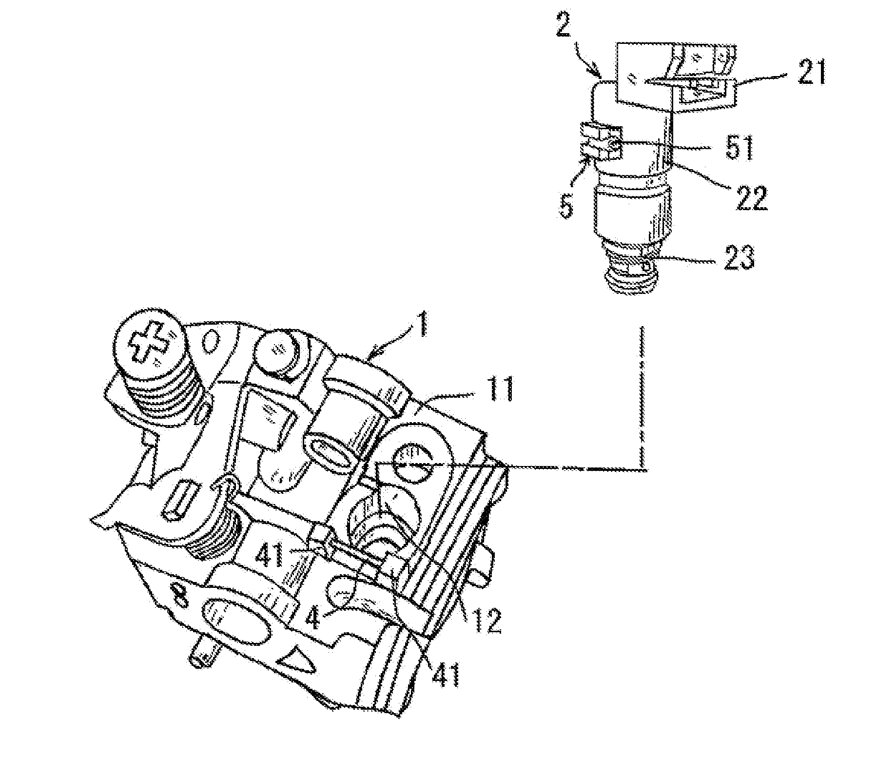
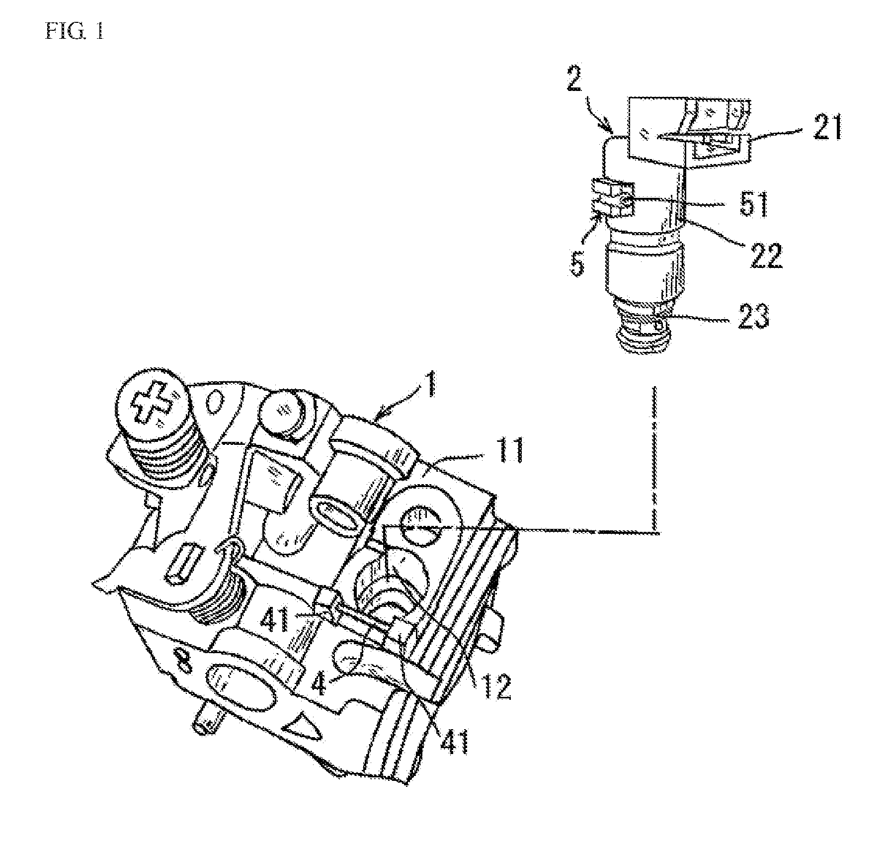
[0022]FIG. 1 shows a preferred embodiment of a carburetor unit 1 and a solenoid valve 2 of the present invention. As with conventional solenoid valves, the solenoid valve 2 has a hard synthetic resin cover 22 in which a connector 21 is formed as a protrusion for supplying power to a built-in solenoid (not shown in the drawings), and an insertion portion 23 which is exposed at the tip.

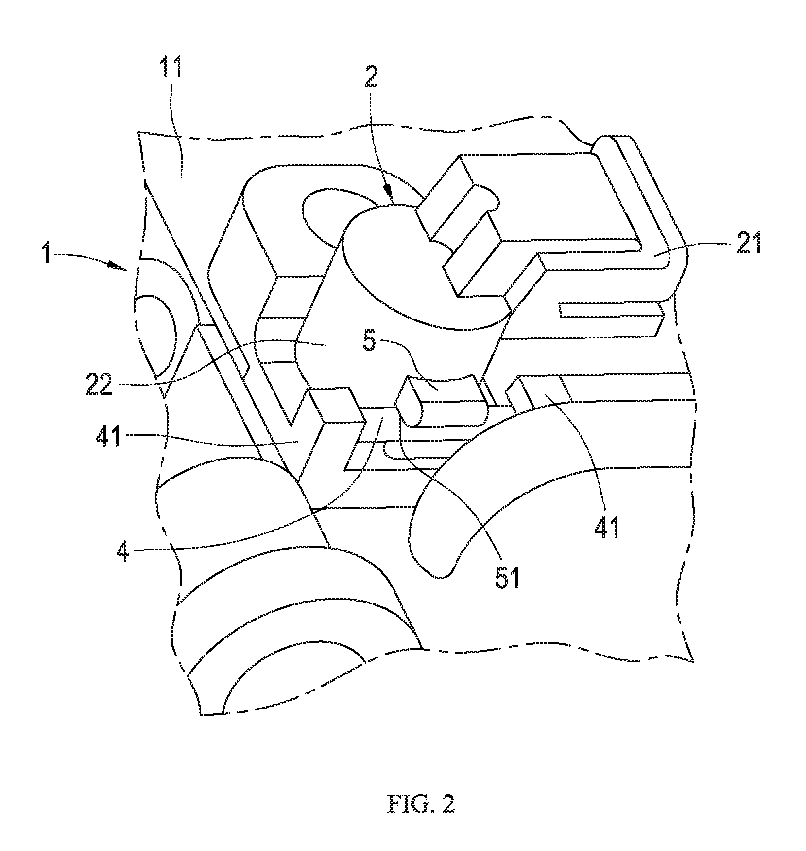
[0023]The carburetor unit 1 of the present embodiment is formed through aluminum die cast molding or the like. An opening 12, which communicates with a fuel supply path formed inside (not shown in the drawings), is formed in a surface 11 thereof. The tip (insertion portion) 23 of the solenoid valve 2 is inserted into the opening 12.

[0024]A rod-like supporting portion 4 is disposed near the opening 12 at a predetermined distance from the surface 11 of the carburetor unit 1 and extending in a direction which is substantially ...


PUM


Abstract

An attachment structure for a solenoid valve which can be stably attached to and removed from a carburetor unit with a single movement and without increasing the number of parts. A rod-like supporting portion is disposed a predetermined distance away from a surface of a carburetor unit and extending in a direction substantially perpendicular to a direction of and installed near an opening in the surface of the carburetor unit. A cylindrical engaging portion extends from a circumferential face of a cylindrical body fitted on the solenoid valve substantially perpendicular to an axial line of the rod-like supporting portion, and forms a groove-like engagement portion which is narrower in diameter than the rod-like supporting portion, whereby the engaging portion, via the groove-like engagement portion, is coupled to and supported by rod-like supporting portion when an insertion portion of the solenoid valve is inserted into the opening.

Description

FIELD OF THE INVENTION[0001]The present invention relates to an attachment structure for a solenoid valve to a carburetor unit which is inserted into an opening formed in one surface of the carburetor unit and communicating with a fuel path therein.BACKGROUND OF THE INVENTION[0002]Conventionally, as shown in FIG. 4, a carburetor unit 1, which is formed by aluminum die cast molding or the like, has a fuel supply path formed inside and a solenoid valve 2 inserted into an opening 12 formed in a surface 11 thereof and which communicates with the fuel supply path.[0003]The solenoid valve 2 typically includes a hard synthetic resin cover 22 placed there over in which a connector 21 is formed as a protrusion for supplying power to a built-in solenoid and an exposed tip (insertion portion) 23 which is inserted into the opening 12. However, if inserted this way it will come out. Therefore, as shown in FIG. 5, for example, the solenoid valve 2 has been attached to the carburetor unit 1 by sec...

Claims


Application Information

Patent Timeline
IPC IPC(8): F02M19/06
CPCF02M7/12F02M19/06F02M7/18
Inventor NONAKA, TAKUMIWATANABE, HIDEKIOKA, HIROYUKI
Owner ZAMA JAPAN
Why Eureka
Try Eureka