Soil collection attachment with automated gate

a technology of automatic gate and collection tray, which is applied in the direction of earth drilling and mining, earth drilling tools, construction, etc., can solve the problems of time-consuming and labor-intensive cleaning process of excavated materials after digging holes with excavation devices, and does not disclose the attachment of collection tray to movable equipment, so as to reduce time and labor.

Active Publication Date: 2020-08-18
DAKOTA FENCE CO
View PDF28 Cites 1 Cited by
  • Summary
  • Abstract
  • Description
  • Claims
  • Application Information

AI Technical Summary

Benefits of technology

[0008]The soil collection attachment may be used to collect excavated material obtained from digging any hole, including holes for fence posts, holes for planting trees, holes excavated to collect soil samples, or holes excavated for any other purpose. The bucket of the soil collection attachment can preferably collect the excavated materials from several holes before the excavated materials need to be removed from the bucket. The soil collection attachment of the present invention greatly reduces the time and labor required to collect and transport excavated material.
[0009]In a preferred embodiment, the soil collection attachment, when attached to movable equipment, is able to collect, transport, and dispose of excavated material in an automated manner. The functions of the soil collection attachment may be controlled by the equipment operator, through the operation of controls which are located in the operator control area of the movable equipment. Accordingly, the soil collection attachment allows excavated material to be collected, transported, and disposed of without the need for manual labor.

Problems solved by technology

This procedure for cleaning up the excavated materials after digging a hole with an excavation device is time-consuming and labor-intensive.
U.S. Patent Application Publication No. 2003 / 0097772 does not disclose a means for closing the aperture in the collection tray, and does not disclose a means for transporting and disposing of the excavated material in an automated manner.
It also does not disclose the attachment of a collection tray to movable equipment such as a loader.
However, those patents do not disclose an automated means for opening or closing the aperture in the collection tray, and do not disclose a means for transporting and disposing of the excavated material in an automated manner.
They also do not disclose the attachment of a collection tray to movable equipment such as a loader.

Method used


Image

  • Soil collection attachment with automated gate
  • Soil collection attachment with automated gate
  • Soil collection attachment with automated gate

Examples


Embodiment Construction

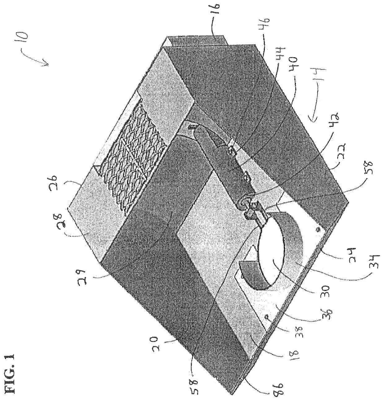
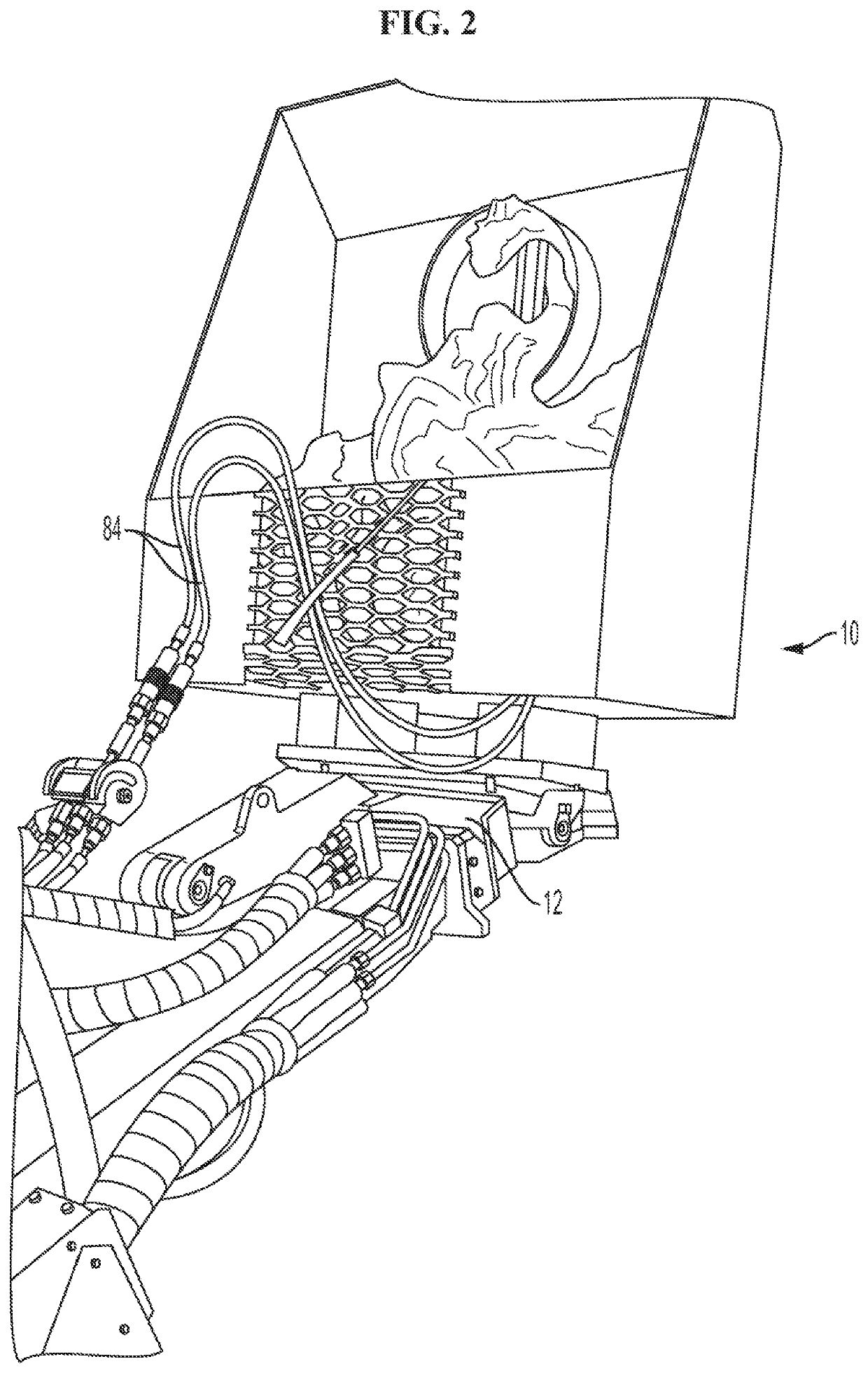
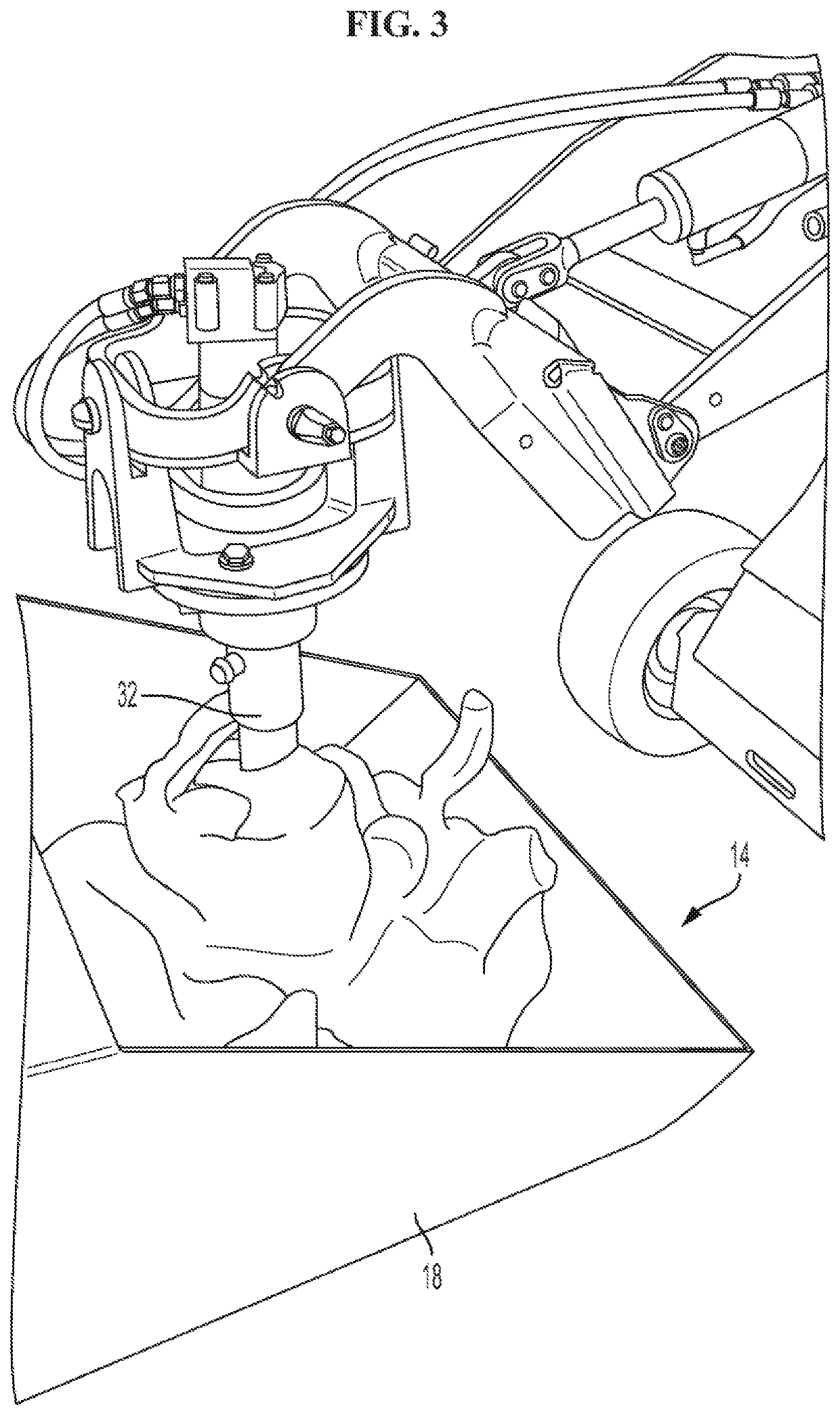
[0026]FIG. 1 depicts a soil collection attachment 10. The soil collection attachment 10 is an attachment for movable equipment including, but not limited to, a skid steer loader or a front-end loader. FIG. 2 shows soil collection attachment 10 attached to the boom 12 of a skid steer loader. The soil collection attachment 10 includes a bucket 14 and an attachment plate 16. The bucket 14 includes a bottom panel 18, side panels 20, 22, a front panel 24, a back panel 26, and a top panel 28.

[0027]A curved plate 29 may also be included in the bucket 14. The curved plate is positioned in front of back panel 26. Without a curved plate 29, excavated material may collect and become compacted in the joint between bottom panel 18 and back panel 26. By eliminating a 90° angle in the back of bucket 14, the curved plate 29 reduces or eliminates the compaction of the excavated material, and therefore makes it easier for the bucket to be emptied. In locations with wet soil or clay, the curved plate ...


PUM


Abstract

A soil collection attachment for movable equipment is described. The soil collection attachment includes a bucket including a bottom panel having an aperture, wherein the aperture is adapted to receive an excavation device such as an auger. A gate which is operated by a hydraulic cylinder is attached to the bottom panel. In a closed position, the gate covers the aperture to prevent excavation materials from falling through the aperture.

Description

TECHNICAL FIELD[0001]The present invention relates to a soil collection attachment for movable equipment such as skid steer loaders. The attachment is used to collect excavated material, including soil, sand, dirt, and clay, which is displaced from the ground when digging a hole.BACKGROUND OF THE INVENTION[0002]When using an excavation device such as an auger, shovel, or post hole digger to dig holes in the ground, the excavated material removed from the hole generally settles around the hole. Manual labor must then be used to collect the excavated material and transport it to another location. For example, people must shovel the dirt, sand, soil, or clay that has collected around the hole into a wheel barrow or other device which can transport the excavated material. The wheel barrow must then be pushed to a location where the excavated material may be deposited, such as up a ramp into the bed of a dump truck. Excavated material is then shoveled out of the wheel barrow. This proced...

Claims


Application Information

Patent Timeline
Patent Type & Authority Patents(United States)
IPC IPC(8): E02F3/40E21B21/015E02F9/22E21B12/06E02F3/32E02F3/34E02F9/28
CPCE02F9/2271E02F3/40E21B12/06E21B21/015E02F3/32E02F9/2833E02F3/3414E02F3/3405E02F3/402E02F3/4075E02F3/962
Inventor CLOUSE, RODNEY
Owner DAKOTA FENCE CO
Why Eureka
Try Eureka