Control device, power receiving device, electronic apparatus, power transmission system, and power supply method

a technology of power receiving device and control device, which is applied in the direction of electric power, electric vehicles, transportation and packaging, etc., can solve the problem of inability to carry out battery discharge operation, and achieve the effect of suppressing wasteful power consumption

Active Publication Date: 2020-08-25
SEIKO EPSON CORP
View PDF16 Cites 1 Cited by
  • Summary
  • Abstract
  • Description
  • Claims
  • Application Information

AI Technical Summary

Benefits of technology

[0012]In this way, wasteful power consumption as a result of the power supply operation of the power supply portion being performed in the charge period in which the battery is charged can be suppressed.
[0026]In this way, even in a removed period in which the power receiving device is removed, supplying the power supply voltage that is based on the battery voltage to the discharging system control portion causes the discharging system to perform discharge control.
[0028]In this way, wasteful power consumption due to discharging power of the battery in the normal power transmission period in which the battery is charged can be suppressed. Also, in the case where the first mode is set, discharge power discharged from the battery can be supplied to the power supply target so as to operate by turning on the discharging operation when removal of the power receiving device is detected.
[0036]In this way, the discharging operation can be turned off when removal of the power receiving device is detected by setting the operation mode to the second mode based on a response that the power transmitting device succeeded in landing detection makes to the power receiving device.
[0042]According to another aspect of the invention, in the first mode, when it is detected that the power receiving device has been removed from the power transmitting device, the power supply operation of the power supply portion is turned on. Accordingly, discharge power discharged from the battery can be supplied to the power supply target. On the other hand, in the second mode, when it is detected that the power receiving device has been removed from the power transmitting device, the power supply operation of the power supply portion is turned off. Accordingly, in a removed period in which the power receiving device is removed, wasteful power consumption can be suppressed.

Problems solved by technology

In this way, even when the output voltage of the power receiving portion has decreased, the discharging operation of the battery cannot be performed until the start-up period of the discharging operation has elapsed.

Method used


Image

  • Control device, power receiving device, electronic apparatus, power transmission system, and power supply method
  • Control device, power receiving device, electronic apparatus, power transmission system, and power supply method
  • Control device, power receiving device, electronic apparatus, power transmission system, and power supply method

Examples


Embodiment Construction

[0072]Hereinafter, a preferable embodiment of the invention will be described in detail. Note that the embodiment described below is not intended to unduly limit the content of the invention described in the scope of the claims, and not all configurations described in this embodiment are necessarily essential as solving means of the invention.

[0073]1. Configurations of Power Transmitting Device, Power Receiving Device, and Control Device

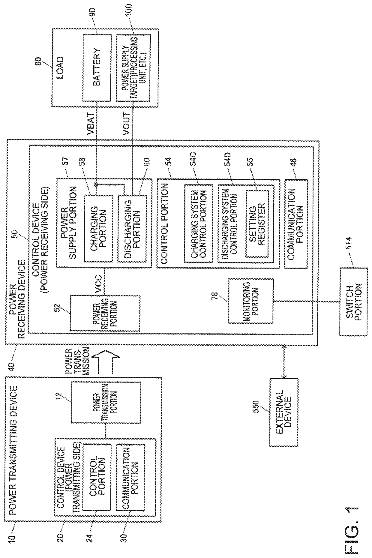
[0074]An exemplary configuration of control devices 20 and 50 of the present embodiment and the power transmitting device 10 and the power receiving device 40 that respectively includes the control devices 20 and 50 is shown in FIG. 1. Note that the configuration of these devices is not limited to the configuration in FIG. 1, and various modifications can be implemented such as omitting a portion of the constituent elements, adding another constituent element (a reporting portion, for example), or changing a connection relationship.

[0075]The power tr...


PUM


Abstract

In the case where it is detected that a power receiving device has been removed from a power transmitting device, a control device turns on a power supply operation of a power supply portion when an operation mode is set to a first mode, and turns off the power supply operation of the power supply portion when the operation mode is set to a second mode.

Description

CROSS-REFERENCE TO RELATED APPLICATION[0001]This application claims priority from Japanese patent application JP 2016-024880 filed Feb. 12, 2016, which is incorporated herein by reference in its entirety.BACKGROUND[0002]1. Technical Field[0003]The present invention relates to a control device, a power receiving device, an electronic apparatus, a power transmission system, a power supply method, and the like.[0004]2. Related Art[0005]In a power transmission system including a power transmitting device and a power receiving device, power transmitted by the power transmitting device is received by a power receiving portion of the power receiving device, and the power receiving device supplies power to a load based on the received power. For example, technologies disclosed in JP-A-2008-206232 and JP-A-2009-11129 are known technologies of a contactless power transmission system. The contactless power transmission system uses electromagnetic induction or the like, and enables power transm...

Claims


Application Information

Patent Timeline
Patent Type & Authority Patents(United States)
IPC IPC(8): H02J50/90H02J7/04H02J7/02H02J50/80H02J50/12
CPCH02J50/90H02J50/12H02J50/80H02J7/007H02J7/025H02J7/0068H02J7/04
Inventor ONISHI, KOTA
Owner SEIKO EPSON CORP
Why Eureka
Try Eureka