Mist removal system and mist removal method

a technology of mist removal system and mist removal method, which is applied in the direction of electrical programme control, program control, instruments, etc., can solve the problems of health hazards, inability to avoid work, and contamination of machine tools and factories, so as to reduce the cost of introduction, suppress and remove the mist efficiently, and curb wasteful power consumption

Active Publication Date: 2017-05-11
FANUC LTD
View PDF0 Cites 1 Cited by
  • Summary
  • Abstract
  • Description
  • Claims
  • Application Information

AI Technical Summary

Benefits of technology

[0020]According to the present invention, since a plurality of mist countermeasure units are coordinately controlled, it is possible to observe and control the mist countermeasure units in the whole of a factory in a unified manner, which makes it possible to suppress and remove a mist efficiently. Moreover, since there is no need to provide individual anti-mist measures unit with excess capacities and it is possible to curb wasteful power consumption which is required to suppress and remove a mist, it is possible to cut down the cost of introduction of those mist countermeasure units and the running cost thereof.

Problems solved by technology

In working using a cutting fluid, a situation in which a machine tool and a factory are contaminated by a mist (particles derived from the discharged cutting fluid scattered in the air by, for example, being raised by a rotary tool) generated at the time of working cannot be avoided.
The mist entering a control panel and a mechanical unit of the machine tool will lead to a mechanical breakdown and, in addition thereto, contamination of the air in the factory may cause a health hazard and accidents caused by poor visibility during work.
The mist countermeasure unit disclosed in Japanese Patent Application Laid-Open No. 2014-161759 described above is independently subjected to ON / OFF-only control under the machine tool to which the mist countermeasure unit is attached, which causes a problem of inefficient mist removal and a lot of waste in power consumption depending on the situation.
For example, the mist collector is generally used in continuous operation, which may cause the mist collector to continue idle running even in a period in which a new mist is not generated while the machine tool is stopped and wastefully continue consuming electric power.
Moreover, considering a case in which a reduction in the concentration of a mist filling the inside of the factory is desired, since the mist concentration varies from hour to hour depending on, for example, the air conditioning state of the factory in addition to the number of machine tools operating in the factory and the working details of each machine tool (in general, a mist is easily generated during hard working), it is inefficient to use only one mist countermeasure unit; however, if all the mist countermeasure units are fully operated continuously with no consideration given to the above-described situation in the factory, the electric power is wastefully consumed.

Method used


Image

  • Mist removal system and mist removal method
  • Mist removal system and mist removal method
  • Mist removal system and mist removal method

Examples


Embodiment Construction

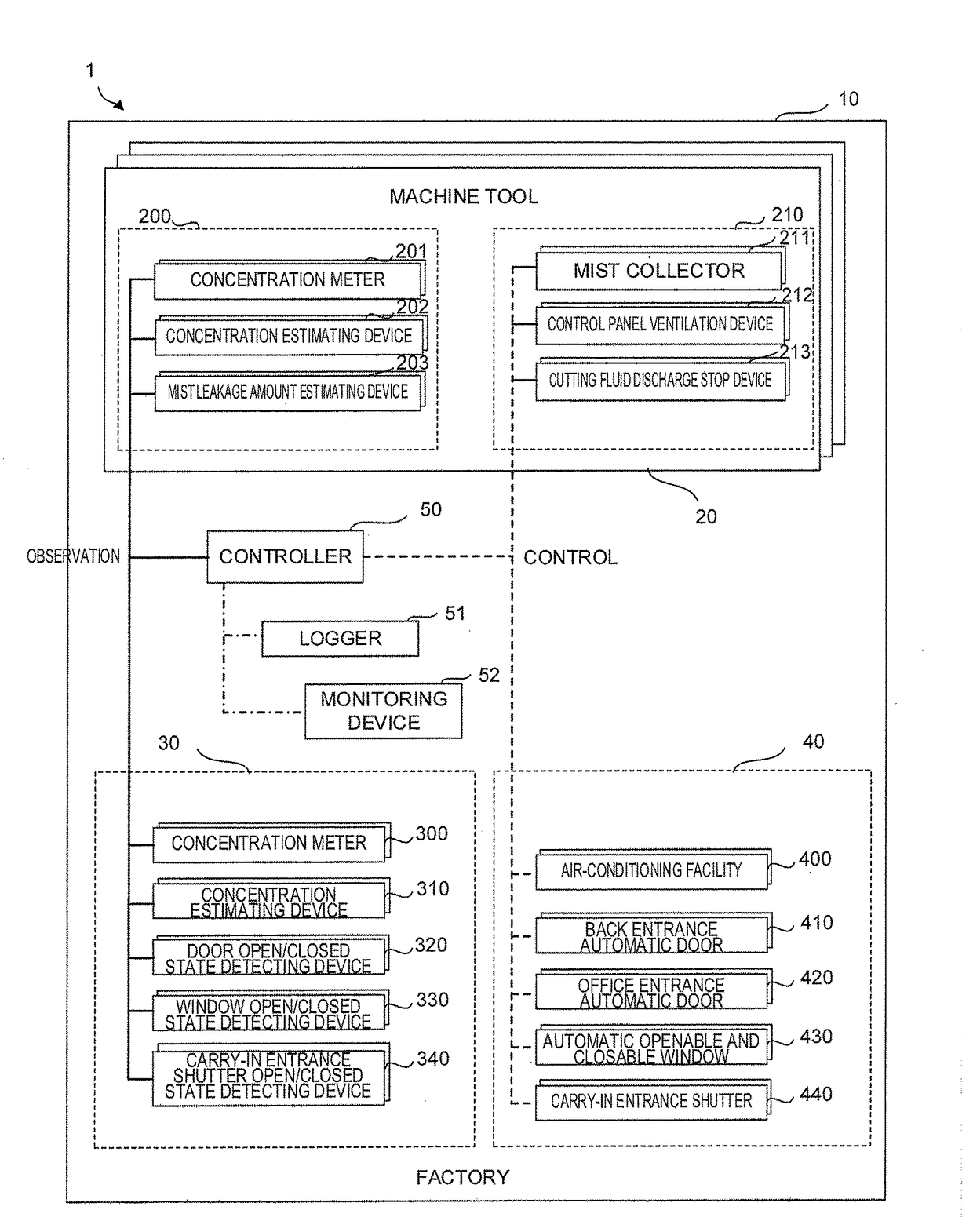
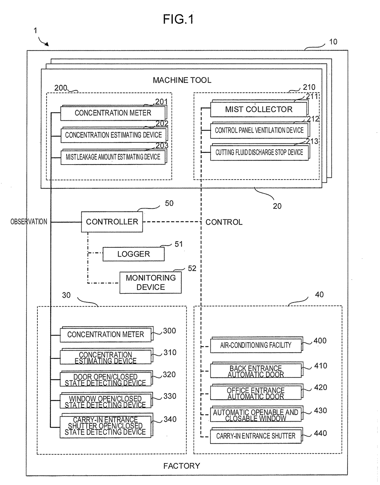
[0028]The present invention solves the problems of the above-described prior art technique by providing a mist removal system provided with a control unit that observes the mist concentration in a region in which removal of a mist is desired to prevent harmful effects on a machine and an operator, such as the inside of a control panel of a machine tool and the space on an office floor of a factory, and coordinately controls a plurality of mist countermeasure units (for example, a mist collector and an air conditioner of the factory) based on the observation results thus obtained.

[0029]The mist removal system of the present invention performs, as an example, control by which the mist removal system adjusts the air conditioner in the factory while reducing the mist concentration in the machine tool, which is a mist generation source, by the mist collector and coordinately combines ON / OFF of the mist collector and the air conditioner in an efficient manner in order to reduce the mist c...


PUM


Abstract

A mist removal system includes an observation unit that observes a situation related to the mist concentration in a factory, a first mist countermeasure unit that reduces the mist concentration in a machine tool, a second mist countermeasure unit that reduces the mist concentration in the factory, and a control unit. The control unit controls observation by the observation unit and interlocking operation of the first mist countermeasure unit and the second mist countermeasure unit. Furthermore, the control unit determines the control details of interlocking operation of the first and second mist countermeasure units based on the observation results of the mist concentration obtained by the observation unit.

Description

BACKGROUND OF THE INVENTION[0001]1. Field of the Invention[0002]The present invention relates to a mist removal system and a mist removal method that reduce the mist concentration in a machine tool and the mist concentration in a factory in which the machine tool is installed.[0003]2. Description of the Related Art[0004]In working using a cutting fluid, a situation in which a machine tool and a factory are contaminated by a mist (particles derived from the discharged cutting fluid scattered in the air by, for example, being raised by a rotary tool) generated at the time of working cannot be avoided. The mist entering a control panel and a mechanical unit of the machine tool will lead to a mechanical breakdown and, in addition thereto, contamination of the air in the factory may cause a health hazard and accidents caused by poor visibility during work.[0005]Thus, in the past, a technology for mist suppression and removal (hereinafter referred to as a mist countermeasure unit), such a...

Claims


Application Information

Patent Timeline
Patent Type & Authority Applications(United States)
IPC IPC(8): B23Q17/00G05B19/4065B23Q11/00
CPCB23Q17/007G05B2219/50276G05B19/4065B23Q11/00G05B19/418B08B15/00B08B17/00
Inventor MASAKAWA, TAKASHI
Owner FANUC LTD
Why Eureka
Try Eureka