Power consumption display unit for machine tool

a technology of power consumption display unit and machine tool, which is applied in the direction of computer control, program control, instruments, etc., to achieve the effect of confirming wasteful power consumption

Inactive Publication Date: 2014-12-30
JTEKT CORP
View PDF5 Cites 0 Cited by
  • Summary
  • Abstract
  • Description
  • Claims
  • Application Information

AI Technical Summary

Benefits of technology

[0007]The invention is made in light of the above-described circumstances, and it is an object of the invention to provide a power consumption display unit for a machine tool, which makes it possible to visually confirm wasteful power consumption.
[0008]According to a feature of an example of the invention, the power consumption in the non-machining state is displayed, and therefore the operators are able to ascertain how much power is possibly wasted. However, the non-machining state includes a state immediately before the machining state, and the power consumption in this state is not a waste. Therefore, it cannot be said that the power consumption in the non-machining state is entirely a waste, but there is a possibility that the power consumption may be at least partially a waste. Therefore, the invention makes it possible to visually confirm the power consumption that may be possibly a waste. Thus, the operators are given an opportunity to examine a wasteful part of the power consumption. This creates a possibility to reduce the power consumption.
[0010]According to another feature of an example of the invention, the non-machining state is divided into the operation standby mode and the operation standby OFF mode, and the power consumption in the operation standby mode and that in the operation standby OFF mode are displayed. Thus, the operators are able to ascertain in more detail how power is consumed. As a result, wasteful power consumption is further reduced.
[0012]In general, the power consumptions of a rotational drive shaft, NC drive shafts, and pumps account for a significant fraction of the total power consumption of the machine tool. According to another feature of the invention, by way of example, the operators are able to ascertain the wasteful power consumption included in the power consumptions of these elements, which leads to reduction of the power consumption. Further, with regard to “pumps”, for example, the power consumptions of a coolant pump, a hydraulic pump, and a lubricant pump may be individually displayed. In this case, the power wastefully consumed by each pump is reduced.

Problems solved by technology

Therefore, it cannot be said that the power consumption in the non-machining state is entirely a waste, but there is a possibility that the power consumption may be at least partially a waste.

Method used


Image

  • Power consumption display unit for machine tool
  • Power consumption display unit for machine tool
  • Power consumption display unit for machine tool

Examples


Embodiment Construction

[0018]Hereinafter, embodiments of the invention will be described with reference to the accompanying drawings.

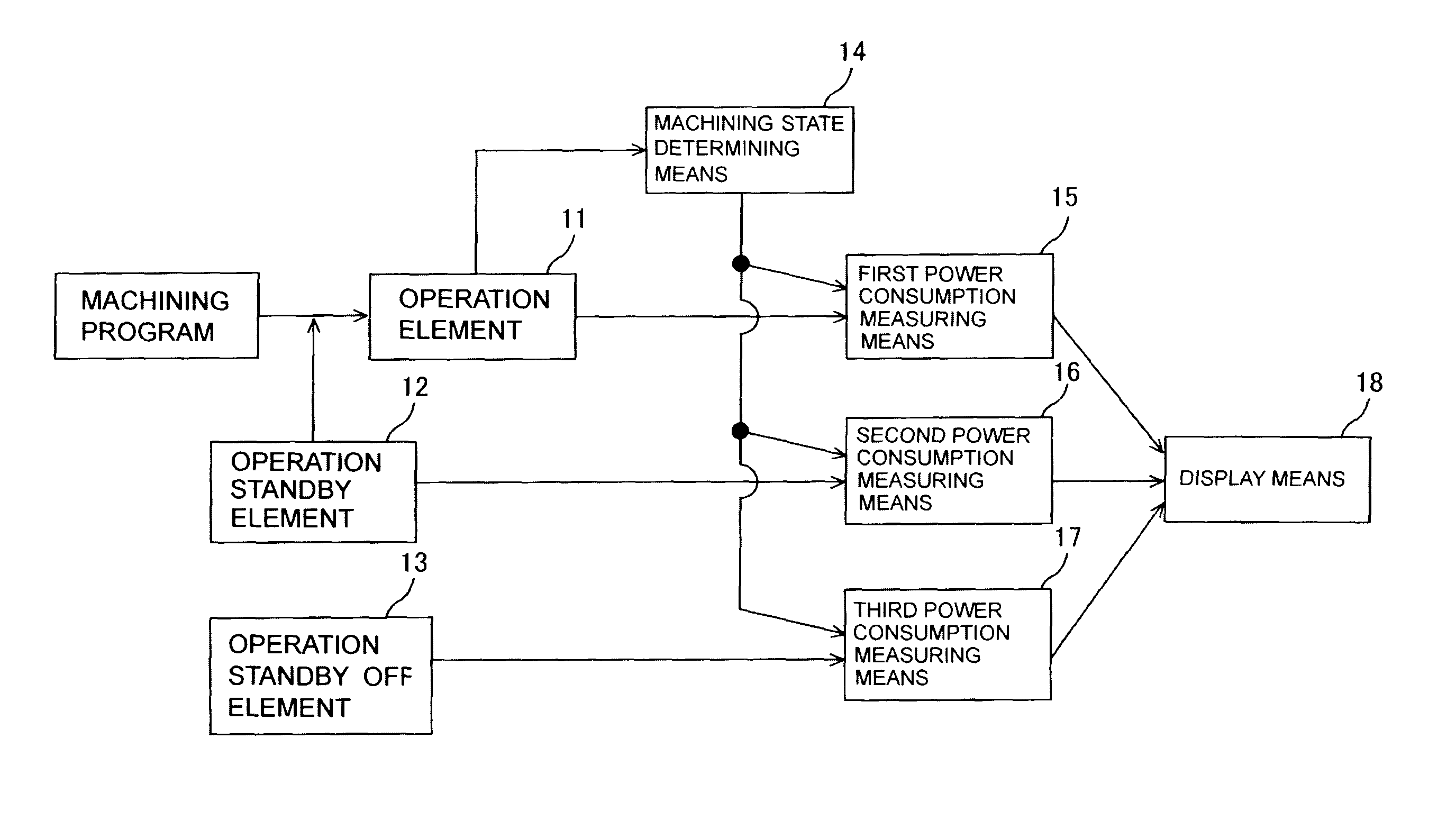
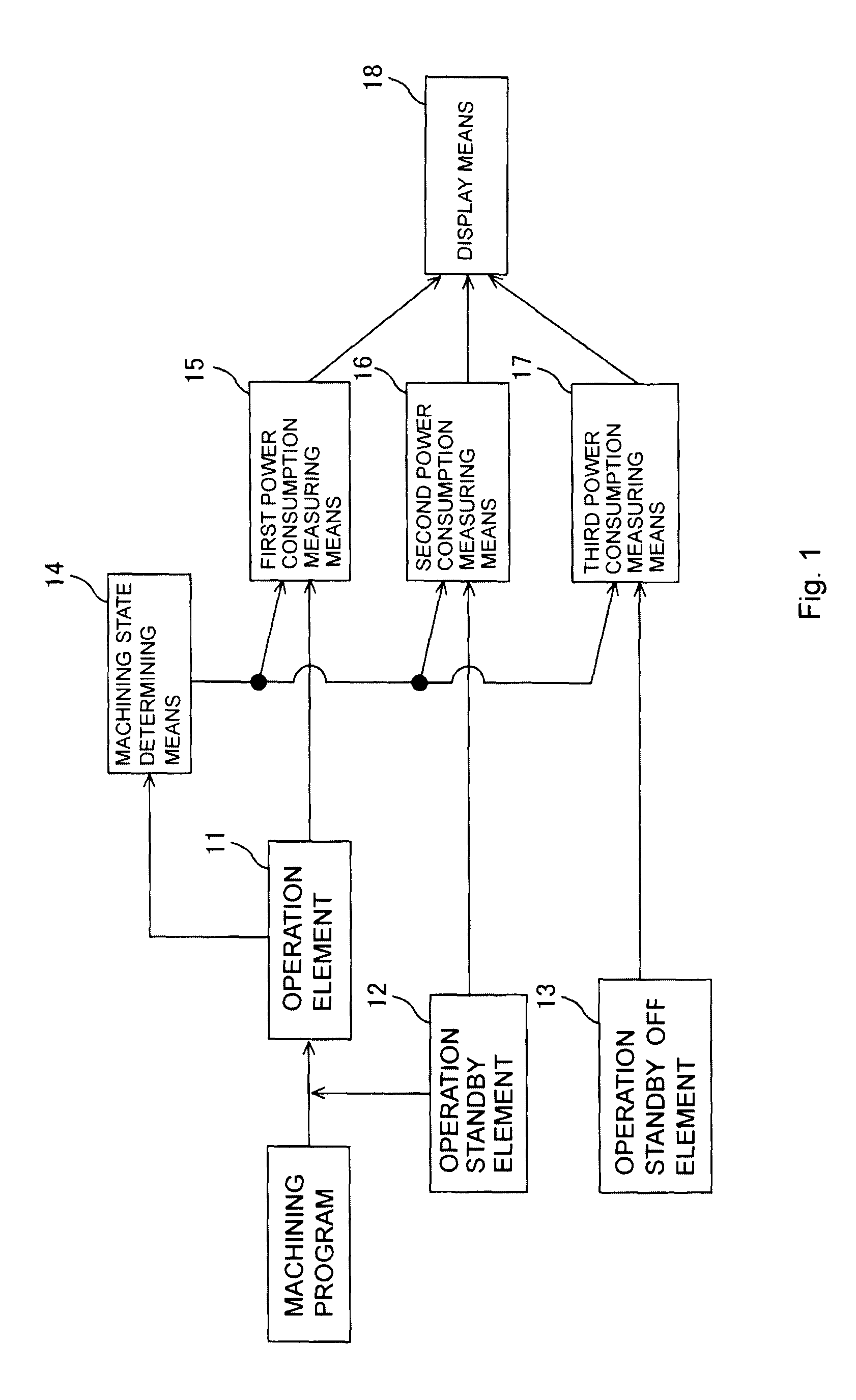
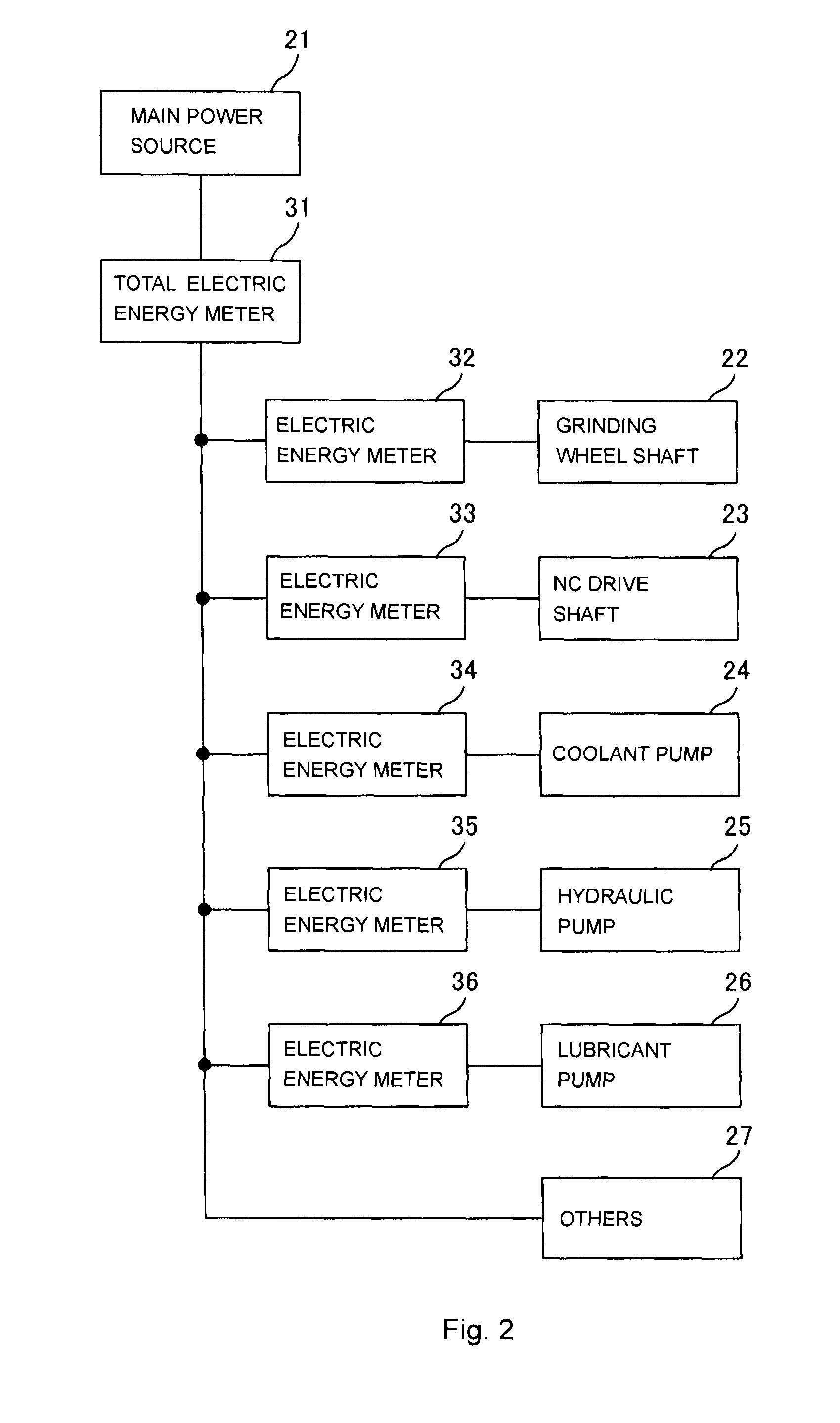
[0019]A power consumption display unit for a machine tool according to an example embodiment of the invention will be described with reference to the accompanying drawings. In the following, a grinding machine used to machine, for example, crankshafts will be described as an example of a machine tool. The grinding machine is constituted of a spindle that supports a crankshaft as a workpiece and operates under numerical control (NC) to rotate the crankshaft, a grinding wheel shaft that supports a grinding wheel and rotates the grinding wheel, and an X-axis drive shaft and a Z-axis drive shaft that operate under numerical control (NC) to cause a relative movement between the workpiece and the grinding wheel. As a matter of course, machine tools in the invention are not limited to the above-described grinding machine, and may be grinding machines used to grind workpieces other ...


PUM


Abstract

A power consumption display unit for a machine tool includes: machining state determining means for determining, when a main power switch used to supply power to a machine tool is ON, whether the machine tool is in a machining state where a machining program is executed to machine a workpiece or in a non-machining state where the machining program is not executed; power consumption measuring means for measuring a power consumption of the machine tool during a period where the machine tool is determined to be in the non-machining state by the machining state determining means; and display means for displaying the power consumption measured by the power consumption measuring means.

Description

INCORPORATION BY REFERENCE / RELATED APPLICATION[0001]This application claims priority to Japanese Patent Application No. 2010-241136 filed on Oct. 27, 2010 the disclosure of which, including the specification, drawings and abstract, is incorporated herein by reference in its entirety.BACKGROUND OF THE INVENTION[0002]1. Field of the Invention[0003]The invention relates to a power consumption display unit for a machine tool.[0004]2. Discussion of Background[0005]For example, U.S. Pat. No. 6,526,360 describes detecting power consumption in each cycle of a repeated operation and then displaying the power consumption of a power-consuming element or a machine in each cycle.[0006]Recently, there have been demands for reduction of wasteful power consumption in a machine tool. However, it is difficult to ascertain how much power is wastefully consumed and where in a machine tool power is wastefully consumed.SUMMARY OF THE INVENTION[0007]The invention is made in light of the above-described ci...

Claims


Application Information

Patent Timeline
Patent Type & Authority Patents(United States)
IPC IPC(8): G05B19/409G05B15/02G01R21/00G01R21/06
CPCG05B2219/23102G05B19/409G05B15/02G05B2219/23179G05B2219/31414
Inventor HASEGAWA, KOJISUGIURA, HIROTAKAKOJIMA, TAKESHI
Owner JTEKT CORP
Why Eureka
Try Eureka